(4) In sert piston guide ring (2) (Fig. 179). Th e
valve (1) in th e piston guide rin g must be on top.
(5) In sert disc spring (14) (Fig. 178) and spring
plate (15). Inser t disc spring with the cur vature
towar ds t he spring plate
(6) Pla ce Mult i-use Spring Compressor 8900 on the
disc spr ing (14) and compress the spring u ntil the
groove for the sn ap-ring is exposed.
(7) In sert snap-r ing (16).
NOTE: Pay attention to sequence of discs. If the
original clutch discs are reused, be sure to return
the disc identified on disassembly as belonging on
top of the disc spring (3) to its original location.
Place new friction multiple-discs in ATF fluid for
one hour before installing.
(8) In sert disc spr ing (3) and multiple-disc pa ck (2)
in the B2 outer multiple-disc carrier.
(9) In sert snap-r ing (1).
NOTE: During the measurement the snap-ring (8)
must contact the upper bearing surface of the
groove in the outer multiple-disc carrier.
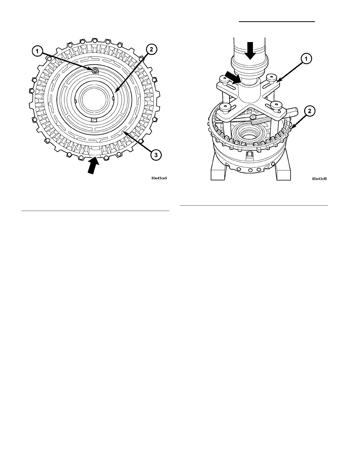
(10) Measure the B2 clut ch pack cleara nce by
mounting th e P ressing Tool 8901 (1) (Fig. 180) on
outer m ultiple disc.
(11) Usin g a lever press, com pr ess the pressing
tool as far as the stop (th en the ma rking ring is still
visible, see small a rrow).
Fig. 179 B2 Piston and Piston Guide Ring
1 - VALVE
2 - PISTON GUIDE RING
3 - B2 PISTON
Fig. 180 Measure B2 Clutch Clearance
1 - PRESSING TOOL 8901
2 - B3 PISTON/B2 OUTER DISC CARRIER
21 - 152 AUTOMATIC TRANSMISSION NAG1 - SERVICE INFORMATION VA