SHIFT PRESSURE CONTROL SOLENOID VALVE
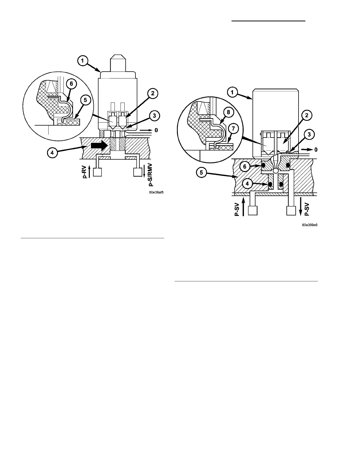
The shift pressure control solenoid valve (1) (Fig.
232) is locat ed in the shell of th e electric valve con -
trol unit and pressed against the shift plate by a
sprin g.
It s pu rpose is to control the sh ift pressure depend-
ing on the continuou sly changing opera ting condi-
tions, such as load a nd gea r change.
The shift pressure regu lating solen oid valve (1) ha s
an in terfer ence fit a nd is sealed off to the va lve body
of the shift pla te (4) by a seal (ar row). The contact
springs (2) at t he solenoid valve enga ge in a slot in
the conductor tracks (3). Th e force of the contact
springs (2) ensures secure conta cts.
OPERATION
When an electrical cu rren t is applied to th e sole-
noid coil, a magnetic field is crea ted wh ich produces
an attraction t o the plu nger, cau sing the plun ger to
move and work again st t he spring pressur e an d the
load applied by th e fluid the valve is con trollin g. The
plunger is nor mally direct ly att ached to the va lve
which it is t o operate. When t he cur rent is rem oved
from th e coil, the a ttraction is removed and the
plunger will return to its origina l position due to
sprin g pressur e.
The plunger is made of a conductive m ater ial and
accomplishes this movement by providing a path for
the magnetic field to flow. By keepin g the a ir gap
between the plunger and t he coil to the minimum
necessar y to allow free movement of the plun ger, the
magnetic field is maxim ized.
UPSHIFT / DOWNSHIFT SOLENOID VALVES
If a solenoid valve (1) (Fig. 233) is act uated by the
TCM, it opens and guides th e contr ol pressur e (p-SV)
to the a ssigned com mand valve. The solenoid valve
rema ins actu ated and ther efore open unt il t he shift-
ing pr ocess is com plete. Th e sh ift pressure (p-SV) to
the comma nd va lve is reduced to zer o as soon as the
power supply to th e solen oid valve is int erru pt ed.
Fig. 232 Shift Pressure Control Solenoid Valve
1 - SHIFT PRESSURE CONTROL SOLENOID VALVE
2 - CONTACT SPRING
3 - CONDUCTOR TRACK
4 - VALVE HOUSING SHIFT PLATE
5 - CONDUCTOR TRACK
6 - CONTACT SPRING
Fig. 233 Upshift/Downshift Solenoid Valves
1 - UPSHIFT/DOWNSHIFT SOLENOID VALVE
2 - CONTACT SPRING
3 - CONDUCTOR TRACK
4 - O-RING
5 - VALVE HOUSING OF SHIFT PLATE
6 - O-RING
7 - CONDUCTOR TRACK
8 - CONTACT SPRING
21 - 174 AUTOMATIC TRANSMISSION NAG1 - SERVICE INFORMATION VA