(4) Remove the wheel and t ire a ssem bly.
INSTALLATION
(1) In st all the wheel a nd tire a ssem bly to th e vehi-
cle.
(2) In st all th e wheel lug studs (SRW) (Fig. 24) and
tighten to specifica tion (Refer to 22 - TIRES/
WHEELS - SPE CIF ICATIONS) See specification
table for model va riations.
(3) In st all the hub cap to the wheel th en inst all
sn ugly the lug nuts t o h old the h ub cap to th e wheel
(DRW) (Fig. 23).
(4) In st all th e wh eel lug n uts (DRW) a nd tight en
to specificat ion (Refer t o 22 - TIRE S/WHEE LS -
SP ECIFICATIONS) See specificat ion table for model
var iations.
(5) Lower th e vehicle.
Fig. 23 FRONT TIRE (DRW)
1 - HUB CAP
2 - LUG NUT WITH HUB CAP HOLD DOWNS
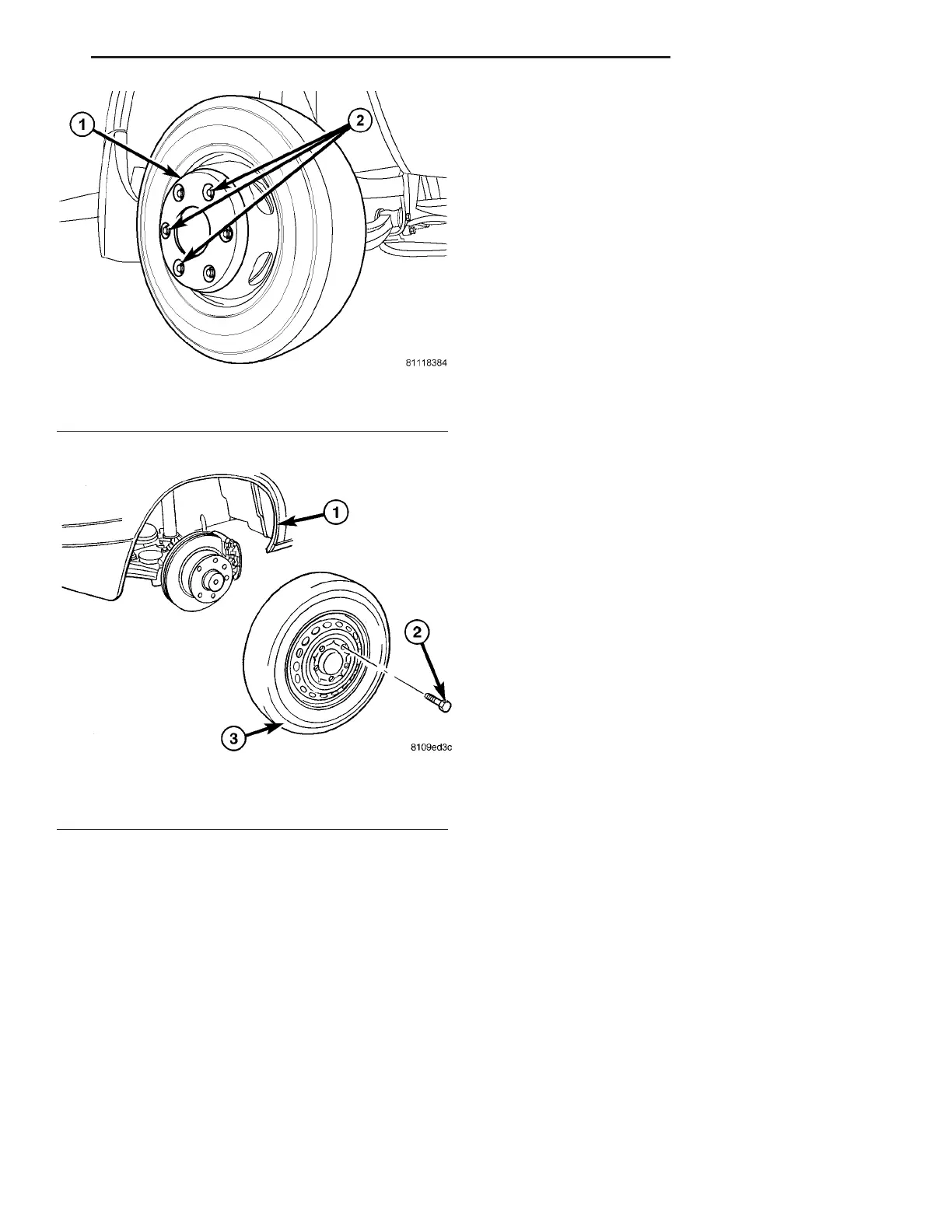
Fig. 24 WHEEL REMOVAL / INSTALLATION
1 - VEHICLE
2 - LUG/STUD
3 - TIRE & WHEEL ASSEMBLY
VA TIRES/WHEELS 22 - 15