CAUTION: Since the rear doors are components
with static functions it is very important that they
are fastened while driving. This prevents excessive
torsion of the vehicle and leaky rear doors. The rear
doors are fastened by adjusting the closing
wedges.
(9) Closin g wedges at bottom mu st be resting free
of pla y on plastic closing pla tes wh en rea r doors a re
closed. To adjust, loosen door hin ges and raise or
lower complete doors.
(10) Loosen u pper closin g wedge screws a nd m ove
top closing wedge up again st plastic closing plate free
of play with rear door closed an d tighten screws to 10
N·m (89 in. lbs.).
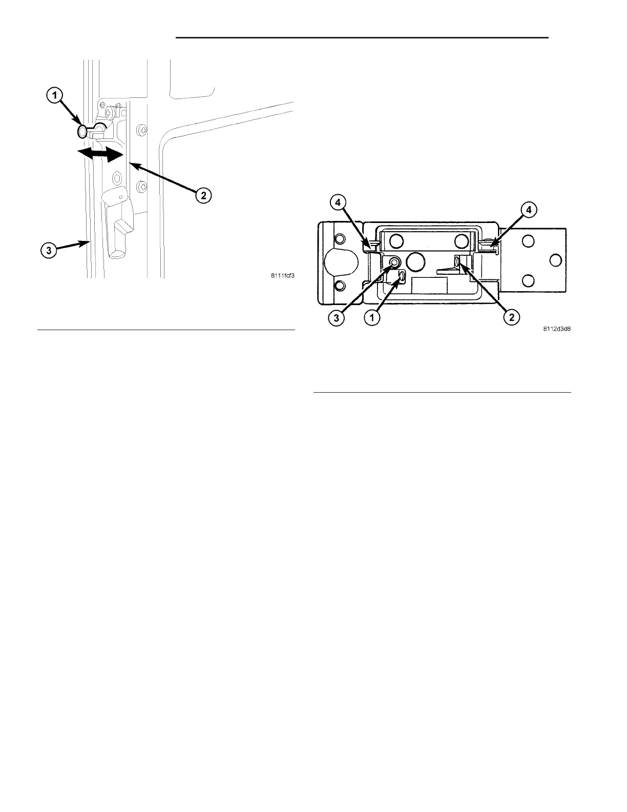
(11) Check a nd adju st the hin ges. On rea r door s,
the retaining ma gnet s shou ld run up to the middle of
the m ating plate a t the side wa ll. If this is not the
case, corr ect as listed. (Fig. 11)
CAUTION: Adjustment range of screw (3) maximum
1 turn (risk of control cam breaking, 4)
• Retaining magnet is too far forward relative to
mating plat e. Turn in adjustmen t scr ew (2) at top
and bot tom hin ge.
• Retaining m agnet is t oo far back relat ive to ma t-
ing plate. Turn ou t adjustment screw (2) at top and
bottom h inge.
• Retaining m agn et is too deep rela tive to mating
plate. Turn in adju stment screw (2) at top hinge,
turn out adju st ment screw (2) at bottom hinge.
• Retaining magnet is too high rela tive t o ma tin g
plate. Turn out a djust ment screw (2) at top hinge,
turn in adj u st ment screw (2) at bottom hinge.
• Retaining m agnet st rikes too hard against mat -
ing pla te. Turn in adjustment screw (1) at top and
bottom h inge.
• Retaining magnet does n ot ma ke contact with
mating plate. Tur n out adjustment screw (1) at t op
and bot tom hin ge.
• Door projects at corner pa neling when closed.
Turn out adj u st ment screw (3) at h inge.
• Door is too far recessed at corn er pa neling wh en
closed. Turn in a djustment screw (3) at hinge.
DOOR GLASS
REMOVAL
(1) Position an assista nt on on e side of the door to
receive t he glass an d weatherstr ip seal.
(2) St art at a n inside, u pper corner. Sepa rate the
seal fr om the window opening. Push th e gla ss and
seal outward from the window open ing. Remove th e
glas s and s e al.
(3) Clean the window open ing.
INSTALLATION
(1) In st all the weat herstrip sea l on t he window
gla ss. Verify t hat th e gla ss is seated in the groove
around the edge of t he seal.
(2) In sert a n installation cord in the wea ther st rip
seal inner groove.
NOTE: Use mineral spirits as a lubricant to aid seal
installation in the window opening.
(3) Position the glass a nd seal in th e window open-
ing.
(4) Pull the installation cord outward and force the
seal lip over the panel flan ge arou nd t he edge of the
openin g.
(5) Seat the sea l inner lip on the panel flange.
Press against the lip a round the edge of the seal.
Fig. 10 STRIKER ADJUSTMENT
1 - STRIKER
2 - LOCK ROD HANDLE ASSEMBLY
3 - LEFT DOOR
Fig. 11 REAR HINGE ADJUSTMENT
1 - ADJUSTMENT SCREW
2 - ADJUSTMENT SCREW
3 - ADJUSTMENT SCREW
4 - CONTROL ARM
23 - 30 D OOR S - R EAR VA