REAR LAT CH
REMOVAL
(1) Disconn ect and isolate battery negative ca ble.
(2) Remove trim pa nel. (Refer to 23 - BODY/
DOORS - SLIDING/TRIM PANEL - REMOVAL)
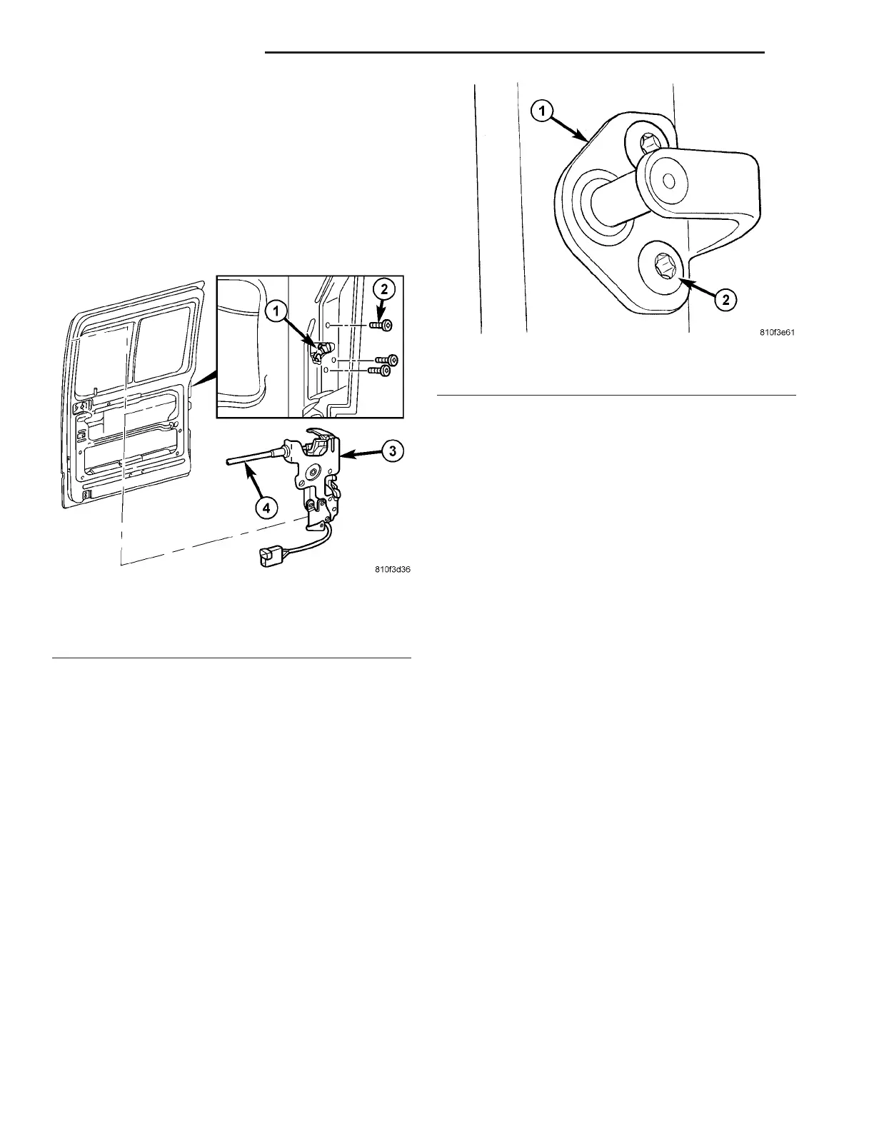
(3) Remove the scr ews and remove th e latch from
door.
(4) Disconn ect electrical conn ector, if equ ipped.
(5) Disconn ect control cable.
INSTALLATION
(1) Connect control cable.
(2) Connect electrical connector, if equ ipped.
(3) Position la tch in door and install screws.
(4) Tighten screws to 10 N·m (89 in. lbs.).
(5) In st all tr im panel. (Refer to 23 - BODY/DOORS
- SLIDING/TRIM PANEL - INST ALLATION)
(6) Connect batt ery n egat ive cable.
REAR LAT CH ST RI K ER
REMOVAL
(1) Open door.
(2) Remove bolt s a nd rem ove str iker. (Fig. 14)
INSTALLATION
(1) In st all striker and bolts.
(2) Tighten bolts to 25 N·m (18 ft. lbs.)
(3) Adjust striker if necessa ry. (Refer to 23 -
BODY/DOORS - SLIDING/SLIDING DOOR -
ADJ USTMENTS)
SLI DI N G DOOR
REMOVAL
(1) Disconn ect and isolate battery negative ca ble.
(2) Remove the screws a nd remove the center
track end piece. (Fig. 15)
(3) Remove the screws a nd remove the st op
bu m per.
(4) Remove the scr ews attachin g th e lower roller
arm to door.
(5) Su pport door with a suit able lift ing device and
roll off the upper and center tracks towards t he r ear
of veh icle.
Fig. 13 REAR LATCH
1 - LATCH OPENING
2 - SCREWS
3 - LATCH ASSEMBLY
4 - CONTROL CABLE
Fig. 14 LATCH STRIKER
1 - STRIKER
2 - BOLTS
23 - 40 DOORS - SLIDING VA