INSTALLATION
Driver’s Side
(1) If equipped, pu ll wire har ness thr ough door.
(2) In st all mirror and bolts.
(3) Tighten t he bolts to 25 N·m (18 ft. lbs.).
NOTE: If vehicle is not equipped with power mir-
rors, skip to step 6.
(4) Connect electrical connector and replace t ape.
(5) In st all t rim pa nel. (Refer to 23 - BODY/DOOR -
FRONT/TRIM PANE L - INSTALLATION)
(6) In st all trim plug.
(7) Connect batt ery n egat ive cable.
Passenger Side
(1) If equipped, pu ll wire har ness thr ough door.
(2) In st all mirror and bolts.
(3) Tighten t he bolts to 25 N·m (18 ft. lbs.).
NOTE: If vehicle is not equipped with power mir-
rors, skip to step 6.
(4) Connect the electr ical connect or.
(5) Connect du st boot to a-pillar.
(6) In st all trim plug.
(7) Connect batt ery n egat ive cable.
SI DE V I EW M I RROR - GLASS
REMOVAL
(1) Disconn ect and isolate battery negative ca ble.
(2) Press mirror glass in at bottom.
(3) Pull m irr or gla ss u p and out of the guides.
(Fig. 5)
(4) Disconn ect th e electr ical connector s, if
equ ipped .
INSTALLATION
(1) Connect the electr ical connect ors, if equipped.
(2) Push mirror glass down into t he guides.
(3) St raight en mir ror gla ss.
(4) Connect batt ery n egat ive cable.
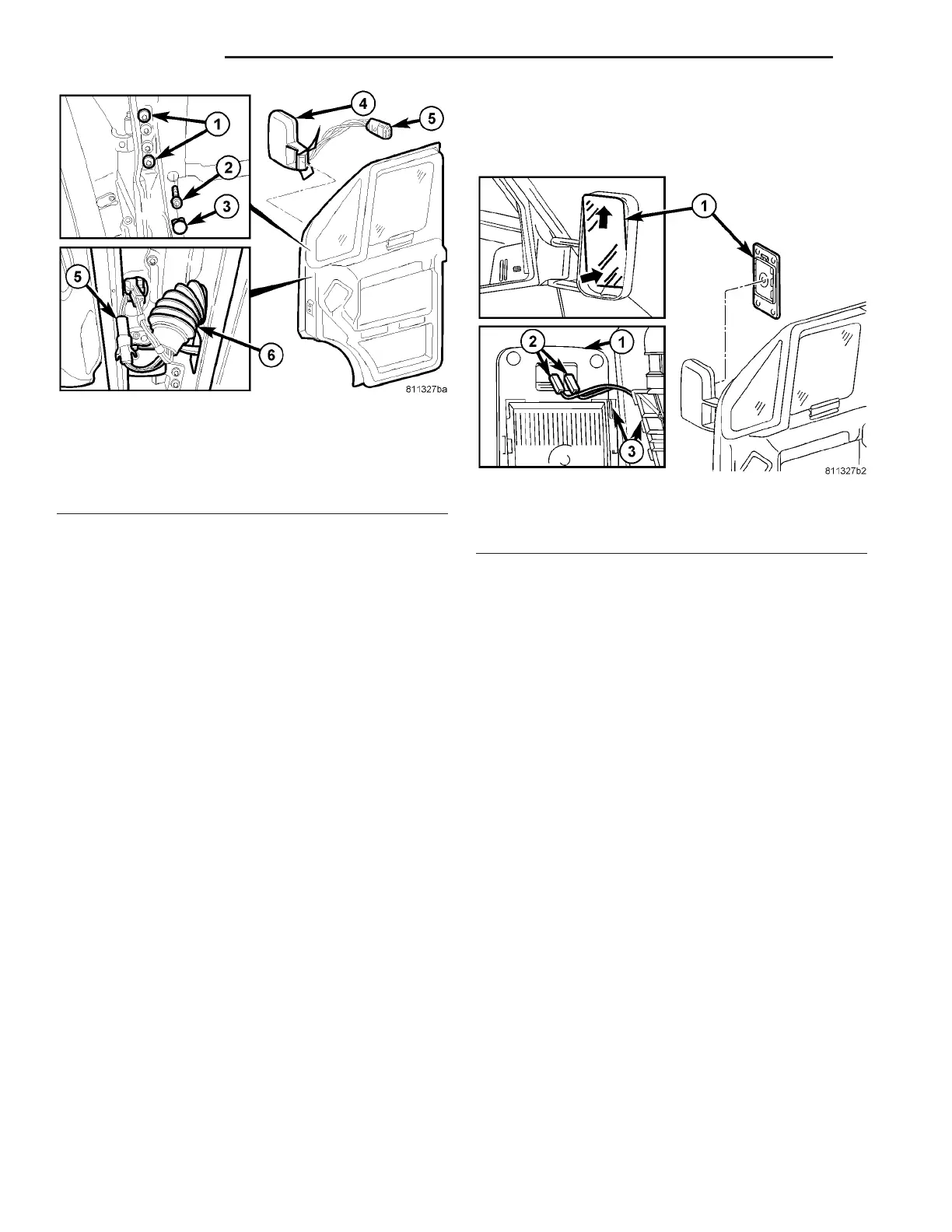
Fig. 4 PASSENGER SIDE MIRROR
1 - OUTER BOLTS
2 - INNER BOLT
3 - TRIM PLUG
4 - MIRROR
5 - ELECTRICAL CONNECTOR
6 - DUST BOOT
Fig. 5 SIDE VIEW MIRROR - GLASS
1 - MIRROR GLASS
2 - ELECTRICAL CONNECTORS
3 - GUIDES
23 - 50 EXTERIOR VA