(4) Disconn ect th e electr ical connector s, if
equ ipped .
INSTALLATION
(1) Position seat in vehicle and connect the electr i-
cal con nector s, if equ ipped.
(2) In st all t he mount ing bolts and t igh ten to 25
N·m (18 ft. lbs.).
(3) In st all the seat belt anch or and bolt.
(4) Tighten a nchor bolt to 35 N·m (26 ft. lbs.).
(5) Connect batt ery n egat ive cable.
SEAT BACK - FRON T
REMOVAL
(1) Disconn ect and isolate battery negative ca ble.
(2) Remove seat cush ion. (Refer to 23 - BODY/
SE ATS/SEAT CUSHION - FRONT - REMOVAL)
(3) Verify tha t seat ba ck is in full upright position.
(4) Disconn ect lumba r support hose, i f equipped.
(Fig. 3)
(5) Remove seat back bolts an d remove sea t
back.
INSTALLATION
(1) Remove stop screw.
(2) In st all seat ba ck locking spline side fir st .
NOTE: For better centering of seat back in the
mounting bore during installation, operate the seat
back release lever once.
(3) In st all the spline side seat back bolt.
(4) In st all remaining seat ba ck side.
NOTE: It may be necessary to press the guide tabs
apart slightly.
(5) In st all the remaining seat back bolt.
(6) Tighten the sea t back bolt s t o 20 N·m (15 ft .
lbs.).
(7) Pla ce sea t back in the foremost position unt il
the h old down sprin g la tches a udibly.
(8) In st all stop bolt and t ighten t o 20 N·m (15 ft.
lbs.).
(9) Connect the lumbar support hose, if equ ipped.
(10) Check seat back operat ion.
(11) In st all th e sea t cush ion. (Refer to 23 - BODY/
SE ATS/SEAT CUSHION - FRONT - INSTALLA-
TION )
SEAT CU SH I ON - FRON T
REMOVAL
(1) Disconn ect and isolate battery negative ca ble.
(2) Move sea t to th e foremost position.
(3) On stan da rd cushion equipped vehicles, rem ove
the fr ont two screws. (Fig. 4)
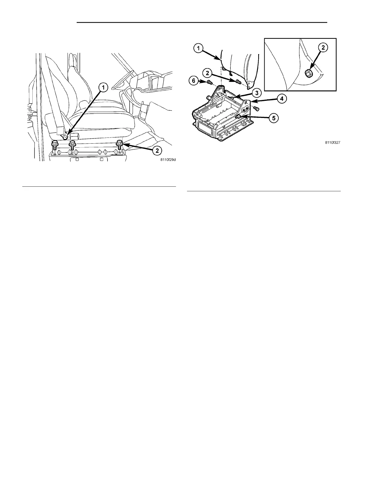
Fig. 2 FRONT SEAT
1 - SEAT BELT ANCHOR BOLT
2 - BOLTS (6)
Fig. 3 FRONT SEAT BACK
1 - SEAT BACK
2 - STOP BOLT
3 - LUMBAR SUPPORT HOSE
4 - GUIDE TAB
5 - RELEASE LEVER
6 - SEAT BACK BOLTS (2)
23 - 80 S EAT S VA