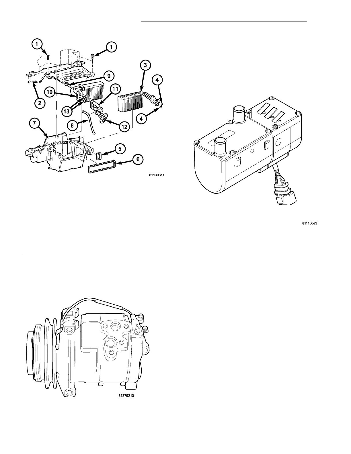
Som e vehicles ar e equ ipped with an addition al
Denso 10S17 A/C compressor mounted to the engine
which is used for the option al rea r A/C system a nd
var ious add-on A/C system s (F ig. 3).
A heater boost er is u sed to aid in wa rming th e
engine coolan t. The heat er booster system can be
switch ed on wh ile th e vehicle is being driven to help
the en gin e r each its nor mal operat ing temper ature
quickly and will help aid in h eating up the air with in
the passenger com pa rtmen t quickly when requested
by the opera tor (Fig. 4).
OPERATION
Outside air ent ers the vehicle t hrough the hood
openin g a t the base of the windshield, and passes
through t he ventilation h ousing loca ted in the engine
compart ment into the hea ter housin g located beh ind
the instrument pa nel. Air flow velocity is adjusted
with the blower motor speed selector thumbwheel on
the A/C-h eater contr ol. Th e air intake open ings must
be kept free of snow, ice, leaves, a nd other obstru c-
tions for the H VAC system to r eceive a sufficient vol-
ume of outside air.
The au toma tic tempera ture cont rol (ATC) system
controls interior tempera ture by takin g actu al valu es
from the t empera ture sensor s and the CAN bus and
comparing them to the nomina l value of t he tem per-
ature con trol switch. The electric pulsed hea ter valve
is then energized depending on the requested qua n-
tity of heat and an elect rica lly-operat ed wa ter pump
gives a nearly constant water flow for exact tem per-
ature regulation. If the solenoid is not energized, th e
coolan t cir cuit to th e heat excha nger is fu lly open. To
control the t empera ture th e solenoid valve is pu lsed
by the ATC in periods of four seconds.
The m ode control knob on the A/C-hea ter con trol is
used to direct the con dition ed air flow to th e selected
air ou tlet s. Th e mode control knob opera tes the m ode
door s by cables conn ected to the m ode door s.
Fig. 2 Heater Housing
1 - SCREW (12)
2 - UPPER HOUSING
3 - A/C EVAPORATOR
4 - EVAPORATOR O-RING SEAL (2)
5 - EVAPORATOR GASKET
6 - VENTILATION HOUSING GASKET
7 - LOWER HOUSING
8 - WIRING HARNESS
9 - BOLT (3)
10 - HEATER CORE
11 - HEATER CORE TUBE ASSEMBLY
12 - HEATER CORE TUBE GASKET
13 - HEATER CORE TUBE O-RING SEAL (2)
Fig. 3 Denso 10S17 A/C Compressor
Fig. 4 Heater Booster
24 - 2 HEATING & AIR CONDITIONING VA