OPERATION
The compr essor clut ch componen ts provide the
mean s to en gage a nd disengage the com pr essor from
the engine serpent ine accessory drive belt. When the
clutch coil is ener gized, it m agnet ically dra ws th e
clutch into contact with th e pulley and drives the
compressor sha ft. When t he coil is n ot energized, the
pu lley freewheels on the clutch h ub bea rin g, which is
pa rt of th e pulley.
The compressor clutch engagement is con trolled by
severa l compon ents:
• A/C switch on the A/C-heater con trol panel
• Evapor ator tempera ture sensor
• A/C pr essu re tr ansducer
• Air temper atur e sensor
• CAN bus messa ges
The compressor clu tch is de-ener gized under an y of
the following condit ions:
• Blocked compressor (th erma l fuse in the pulley)
• Low pressure in the system
• Low eva por ator tempera ture
• Hard a cceleration (WOT)
• High coolant tempera tur es
STAN DARD PROCEDU RE
A / C COMPRESSOR CLUTCH AIR GAP
If a new clutch plate and/or clutch pu lley are being
used, th e air gap between the clut ch plat e and clutch
pu lley mu st be checked using the following proce-
dure:
(1) Usin g feeler gauges, measur e the a ir ga p
between the clutch plate a nd th e clutch pulley fric-
tion sur faces.
(2) If the air gap is not bet ween specifications
(Refer to 24 - HE ATING & AIR CONDITIONING -
SP ECIFICATIONS), add or subt ract shims until th e
desired a ir gap is obtained.
NOTE: The shims may compress after tightening
the compressor shaft bolt. Check the air gap in four
or more places on the clutch plate to verify that the
air gap is still correct. Spin the clutch pulley before
making the final air gap check.
A / C COMPRESSOR CLUTCH BREAK - IN
After a new compressor clutch has been insta lled,
cycle the compressor clut ch approximately twenty
times (five seconds on, th en five seconds off). During
this procedur e, set the heat er-A/C contr ol in th e
Recirculat ion Mode, th e A/C but ton in the on posi-
tion, the blower motor swit ch in the highest speed
position , and the engine speed at 1500 to 2000 rpm.
This procedure (bur nishing) will sea t the opposin g
friction su rfaces and pr ovide a higher compressor
clutch torque capability.
REMOVAL
The refrigerant syst em can rem ain fully-cha rged
du ring compressor clutch, pulley, or coil replacem ent.
The compressor clutch can be serviced in th e vehicle.
(1) Disconn ect and isolate the battery nega tive
cable.
(2) Remove t he serpentine drive belt (Refer to 7 -
COOLING/ACCESSORY DRIVE/DRIVE BEL TS -
REMOVAL).
(3) Disconn ect the engine wire harness conn ector
for the compressor clu tch coil from th e clutch coil
wire harness conn ector on t he top of the compressor.
(4) Remove th e retainer secu rin g the compr essor
clutch coil lead on th e top of the compressor.
(5) Remove th e bolt t hat secu res the compr essor
clutch to the compressor shaft (Fig. 2). If necessary, a
band-t ype oil filter wr ench or stra p wrench can be
placed ar ound the clutch plate to a id in bolt
removal.
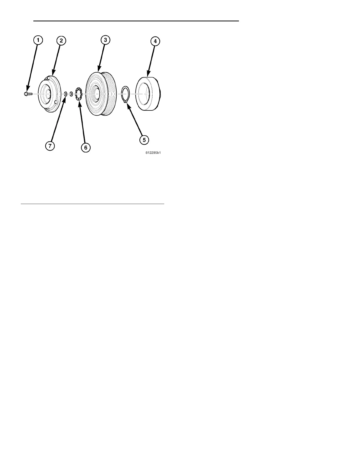
Fig. 1 A/C Compressor Clutch
1 - BOLT
2 - CLUTCH PLATE
3 - PULLEY AND BEARING
4 - FIELD COIL
5 - SNAP RING
6 - SNAP RING
7 - SHIM (2)
VA CONTROLS-FRONT 24 - 9