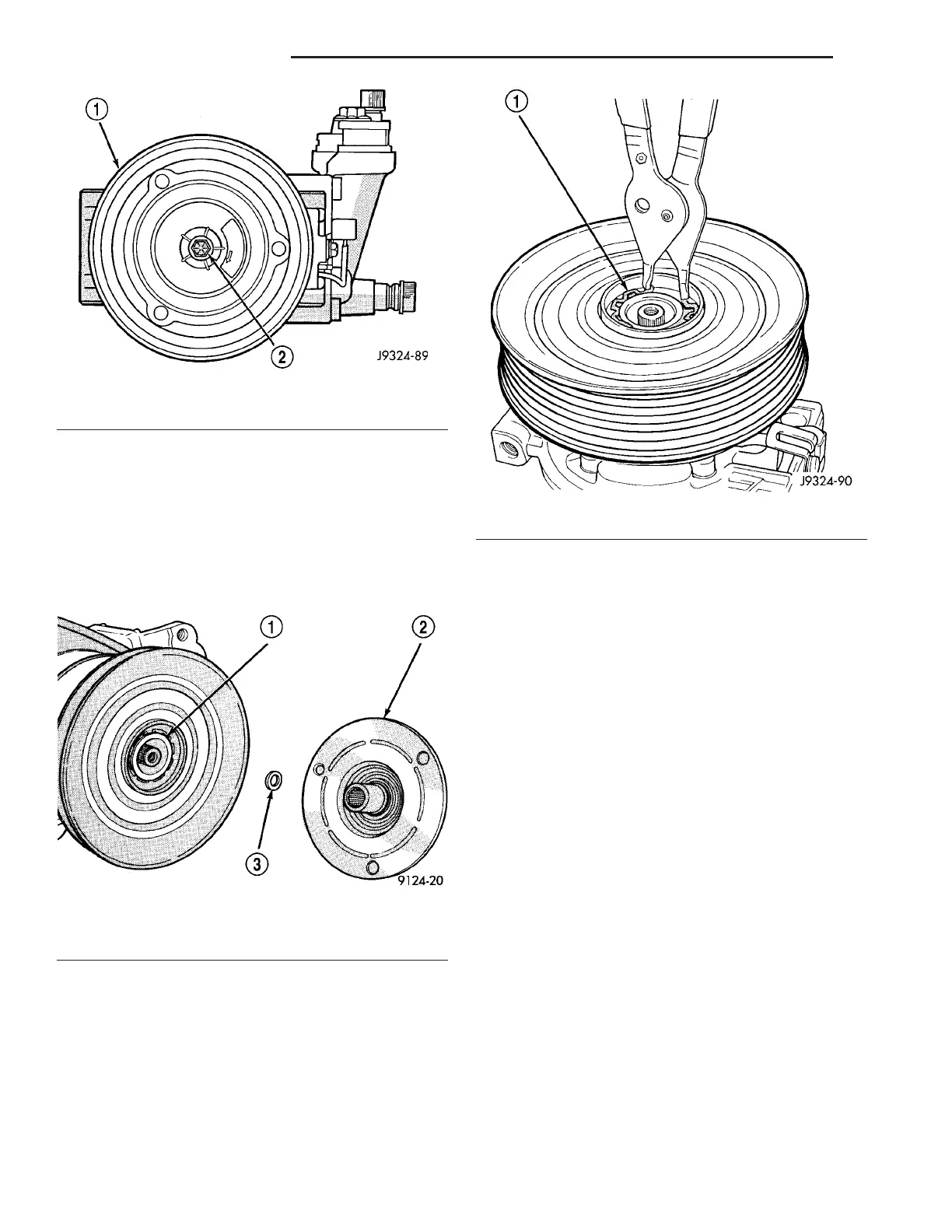
(6) Tap the clutch plate lightly wit h a plastic mal-
let t o r elease it fr om the splin es on th e compressor
sh aft. Rem ove the clutch plat e a nd shim(s) from the
compressor sh aft (Fig. 3). Be certain not to lose
the shim or shims.
CAUTION: Do not pry between the clutch plate and
the pulley to remove it from the compressor shaft.
Prying may damage the clutch plate.
(7) Usin g sn ap ring pliers (Special Tool C-4574 or
equivalent ), rem ove t he external sn ap rin g t hat
secures t he com pr essor clut ch pulley to the front of
the compressor, then slide th e pulley off of the com-
pr essor (F ig. 4).
(8) Remove th e screw that secures the clutch coil
wire har ness connector br acket an d groun d clip to
the t op of the compressor hou sing.
(9) Usin g sn ap ring pliers (Special Tool C-4574 or
equivalent ), rem ove t he external sn ap rin g t hat
secures th e com pr essor clu tch coil to t he front of the
compressor, t hen slide t he clu tch coil off of th e com-
pr essor (F ig. 5).
Fig. 2 Compressor Shaft Bolt and Clutch Plate
1 - COMPRESSOR CLUTCH PLATE
2 - COMPRESSOR SHAFT BOLT
Fig. 3 Clutch Plate And Shim(s)
1 - COMPRESSOR SHAFT
2 - CLUTCH PLATE
3 - CLUTCH PLATE SHIM
Fig. 4 Pulley Snap Ring
1 - SNAP RING
24 - 10 CONTROLS-FRONT VA