INSPECTION
Compressor clutch componen ts shou ld always be
inspected closely before th ey are reinstalled. The
clutch plat e a nd clu tch pulley a re mated at the fac-
tory using a bur nishing operation . No a ttem pt should
be made to separately replace t he compressor clut ch
pu lley or clutch plate. Th e clutch coil may be serviced
separ at ely.
(1) Exa mine t he friction surfa ces of the clutch pul-
ley and the clutch pla te for wear. Th e clutch pulley
and clut ch plate shou ld be r eplaced if th ere is exces-
sive wear or scoring.
(2) Exa mine t he friction surfa ces of the clutch pul-
ley an d th e clutch plate for oil conta mination. If the
friction su rfaces are oily, the clu tch pu lley a nd clutch
plate sh ould be replaced. Also inspect the shaft and
nose area of t he compr essor for oil. Remove the felt
pa cking from a roun d the compressor shaft in the
compressor front cover. If t he felt is sat urated with
oil, th e compressor front sha ft seal i s leaking and the
compressor will a lso ha ve to be replaced.
(3) Check t he clu tch pulley bearing for r oughness
or excessive lea kage of grea se. Repla ce the clutch
pu lley an d clutch pla te if the bearing is fau lty.
INSTALLATION
(1) Align the dowel pin on the back of the clutch
field coil with the hole in the com pressor front cover,
and position t he clut ch coil on to th e compressor. Be
certa in t hat the cluch coil wire harness leads a re
pr operly orien ted and rou ted so tha t they are not
pinched between the com pr essor fron t cover and the
clutch coil.
NOTE: A new snap ring must be used to secure the
clutch coil to the compressor. The bevel side of the
snap ring must face outward.
(2) Usin g sn ap ring pliers (Special Tool C-4574 or
equivalent ), in st all the externa l sn ap rin g t hat
secures the clu tch coil to the fron t cover of the com-
pr essor. The bevel side of the sna p ring must be fac-
ing out ward a nd both snap r ing eyelet s must be
orien ted to the right or left of the clutch coil dowel
pin on th e compressor. Be certain that the sna p ring
is fully and properly seated in the groove.
CAUTION: If the snap ring is not fully seated in the
groove it will vibrate out, resulting in a clutch fail-
ure and severe damage to the compressor front
cover.
(3) In st all and tigh ten the screw that secur es th e
clutch coil wire harness connect or br acket and
ground clip t o the top of the compressor h ousing.
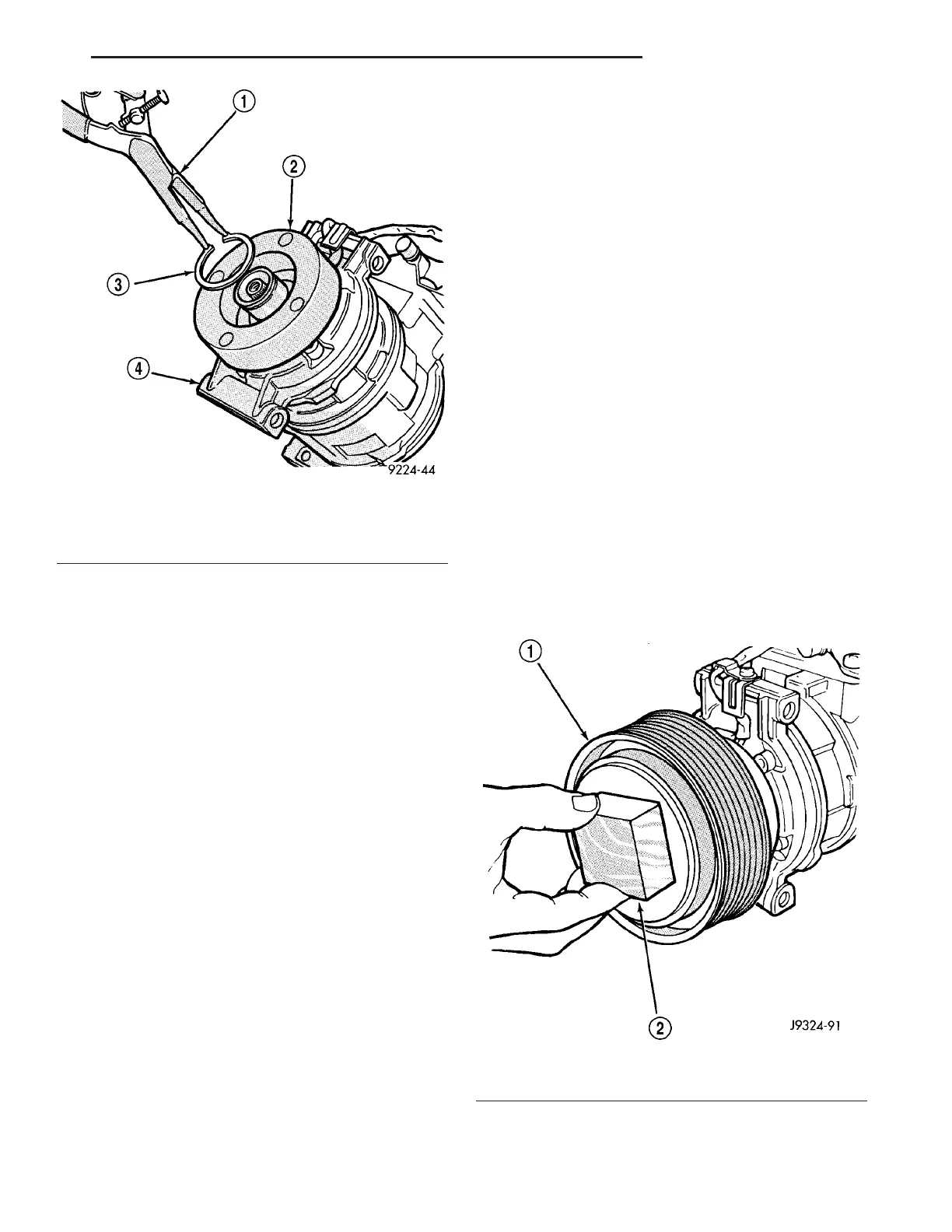
(4) In st all th e pulley onto th e front of the compres-
sor. If necessary, pla ce a block of wood on the frict ion
su rface a nd tap gently with a ha mmer (F ig. 6).
CAUTION: Do not mar the friction surfaces of the
pulley.
(5) Usin g sn ap ring pliers (Special Tool C-4574 or
equivalent ), insta ll t he ext erna l snap ring (bevel side
facin g outward) t hat secures t he clutch pu lley to the
Fig. 5 Clutch Coil Snap Ring
1 - SNAP RING PLIERS
2 - CLUTCH COIL
3 - SNAP RING
4 - COMPRESSOR
Fig. 6 Pulley Assembly Install
1 - PULLEY ASSEMBLY
2 - WOOD BLOCK
VA CONTROLS-FRONT 24 - 11