radio (Fig. 7). The A/C-hea ter control contains a rot a-
ry-type tem perat ure con trol, a rota ry-t ype mode con-
trol, a t humbwheel-type blower motor speed control
and an A/C mode push butt on switch a nd indica tor
lam p. The A/C-heater control also features a pu sh
butt on switch and indicator la mp for th e r esidual
engine hea t utilizat ion (REST) function, ca bin heater
or the h eater booster (as equipped).
OPERATION
To control the interior tempera ture, the A/C-h eater
control uses the actual valu es from the tem per atu re
sensors and th e CAN bus and compa res them with
the nominal valu e of the temper ature cont rol switch .
The A/C-h eater control is diagnosed using a DRBIII!
sca n tool. Refer to Body Dia gnostic Procedu res.
The A/C-heater contr ol is diagnosed using a
DRBII I! sca n tool. Refer t o Body Dia gnostic Proce-
dures.
The A/C-hea ter cont rol cannot be adjusted or
repaired a nd, if faulty or dam aged, it must be
repla ced.
REMOVAL
WARNING: To avoid personal injury or death, on
vehicles equipped with airbags, disable the supple-
mental restraint system before attempting any
steering wheel, steering column, airbag, seat belt
tensioner, impact sensor, or instrument panel com-
ponent diagnosis or service. Disconnect and isolate
the battery negative (ground) cable, then wait two
minutes for the system capacitor to discharge
before performing further diagnosis or service. This
is the only sure way to disable the supplemental
restraint system. Failure to take the proper precau-
tions could result in accidental airbag deployment.
(1) Disconn ect and isolate the negat ive ba tter y
cable.
(2) Remove t he center bezel from the instrument
pa nel. (Refer to 23 - BODY/INSTRUMENT PANEL/
INSTRUMENT PANE L CE NTE R BEZEL -
REMOVAL).
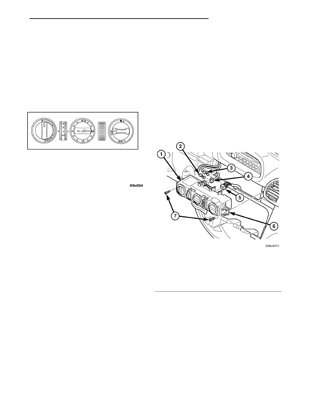
(3) Remove th e two scr ews th at secure the A/C-
heat er control to t he instru ment panel (F ig. 8).
(4) Pull th e A/C-heat er contr ol awa y from t he
instr umen t panel fa r enough to access th e connec-
tions on the back of the contr ol.
(5) Mark and disconnect the t wo contr ol cables
from the A/C-heater contr ol.
(6) Disconn ect th e t wo wir ing h arness connect ors
from the A/C-heater contr ol.
(7) If A/C-hea ter con trol is to be repla ced, r emove
the t wo mounting bra ckets from th e A/C-heater con-
trol.
INSTALLATION
(1) If removed, install the two m ounting bracket s
to th e A/C-hea ter cont rol.
(2) Connect the two wire harness connect ors int o
the back of the A/C-heat er contr ol.
(3) Connect the two con trol cables to the A/C-
heat er control.
NOTE: Install the control cable of bottom adjust-
ment lever to the front adjustment wheel of the A/C-
heater control.
(4) Position the A/C-heat er control into the instru-
ment panel.
Fig. 7 A/C-Heater Control
Fig. 8 A/C-Heater Control
1 - A/C-HEATER CONTROL
2 - CONTROL CABLE
3 - CONTROL CABLE
4 - WIRE HARNESS CONNECTOR
5 - WIRE HARNESS CONNECTOR
6 - MOUNTING BRACKET (2)
7 - SCREW (2)
VA CONTROLS-FRONT 24 - 13