INSTALLATION
(1) Position the rea r A/C clutch relay in to the
pr oper receptacle of t he rela y block located in the
rear A/C eva por ator housing.
(2) Align the A/C clutch relay term inals with the
term inal ca vit ies in th e r elay block recept acle and
pu sh down firmly on the relay until the ter min als
are fully seated.
(3) In st all th e rea r air filter (Refer to 24 - HEAT-
ING & AIR CONDITIONING/DISTRIBUTION -
REAR/AIR FILTE R - INSTALLATION).
(4) Reconnect t he negat ive batt ery cable.
A/CCONDENSERFANRELAY
DESCRIPTION
The rear A/C conden ser fan relay for the r ear A/C
system is an Interna tiona l Stan da rds Organization
(ISO)-t ype relay (Fig. 3). Relays con forming to th e
ISO specifications have common physical dimen sions,
curren t capacit ies, terminal funct ions an d patterns.
The r ear A/C conden ser fan relay is an electr ome-
chanical device tha t u ses a low curr ent input to con-
trol the high cur rent output to the A/C condenser fan
for the r ear hea tin g-A/C system .
The rear A/C condenser fan relay is located in th e
rela y block in the rear A/C eva por ator hou sing.
OPERATION
The ISO-st andar d rear A/C condenser fan r elay is
an electromech anical swit ch that uses a low current
input from the rea r A/C cont rol modu le to cont rol the
high current output to the rear A/C condenser coolin g
fan. Th e movable, common feed r elay conta ct is held
aga inst th e fixed, normally closed relay contact by
spring pressur e. When the elect romagnetic relay coil
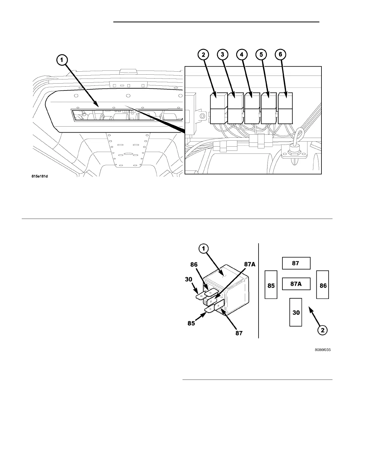
Fig. 2 Rear A/C Clutch Relay
1 - REAR A/C EVAPORATOR HOUSING
2 - BLOWER MOTOR RELAY K204
3 - BLOWER MOTOR RELAY K203
4 - BLOWER MOTOR RELAY K201
5 - REAR CONDENSER FAN RELAY K205
6 - REAR COMPRESSOR RELAY K206
Fig. 3 Rear A/C Condenser Fan Relay
1 - STANDARD ISO RELAY
2 - TERMINAL PATTERN
24 - 26 CON T R OL S - R EAR VA