INSTALLATION
(1) Position t he rear A/C condenser fan rela y into
the proper r eceptacle of the relay block locat ed in the
rear A/C eva por ator housing.
(2) Align the A/C con denser fan relay termina ls
with the t erminal cavit ies in the rela y block recept a-
cle and pu sh down fir mly on the relay u ntil the ter-
minals ar e fully seated.
(3) In st all th e rea r air filter (Refer to 24 - HEAT-
ING & AIR CONDITIONING/DISTRIBUTION -
REAR/AIR FILTE R - INSTALLATION).
(4) Reconnect t he negat ive batt ery cable.
A/CCONTROLMODULE
DESCRIPTION
The r ear A/C control modu le (Fig. 5) is connected
to th e rear A/C blower motor switch, rea r evaporative
temper ature sensor, rear A/C tempera ture cont rol
and the tem perature sen sor.
The rear A/C control module is locat ed in t he upper
left side of the r ear A/C evapora tor housing.
OPERATION
The rear A/C contr ol m odu le is su pplied fused ba t-
tery power through the rear blower switch. The con-
trol module r eceives input signa ls fr om the rear A/C
blower motor switch, rear A/C temper ature contr ol,
rear tempera ture sensor and t he rea r evapora tor
temper ature sen sor when the front A/C switch is
turned on. Th e r ear A/C con trol module uses the
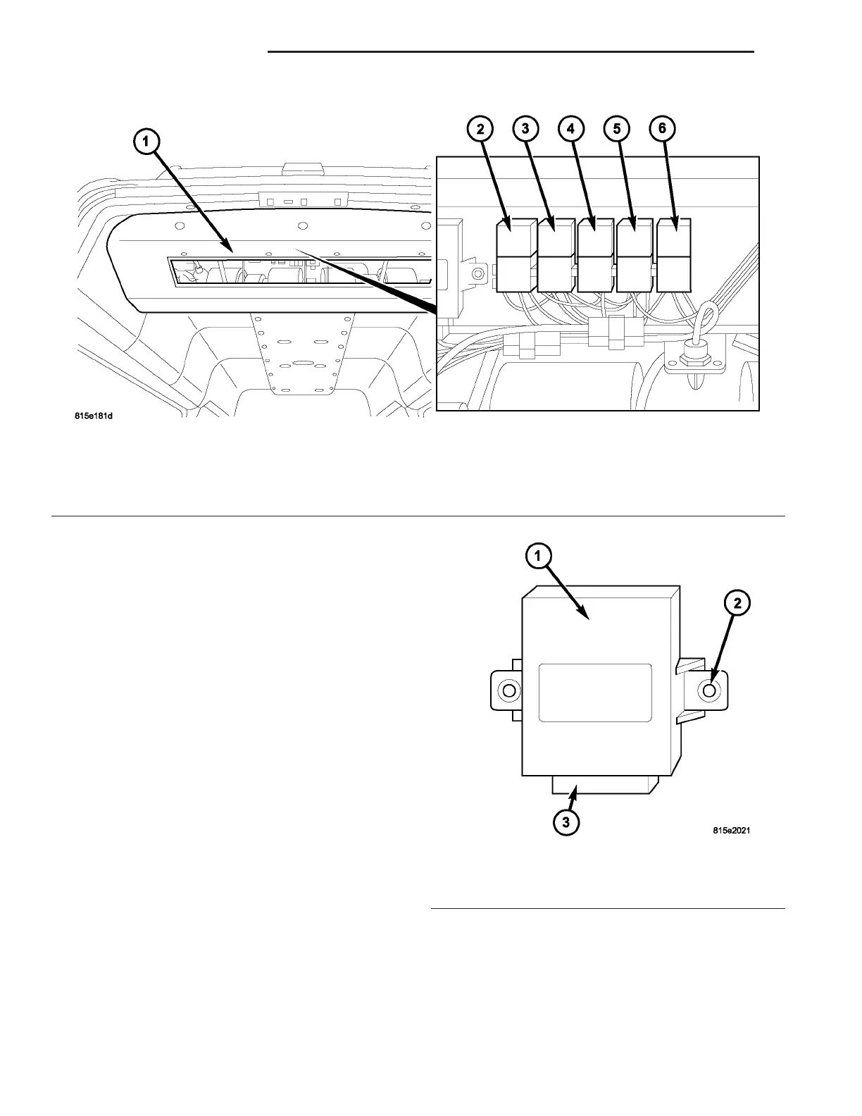
Fig. 4 Rear A/C Condenser Fan Relay
1 - REAR A/C EVAPORATOR HOUSING
2 - BLOWER MOTOR RELAY K204
3 - BLOWER MOTOR RELAY K203
4 - BLOWER MOTOR RELAY K201
5 - REAR CONDENSER FAN RELAY K205
6 - REAR COMPRESSOR RELAY K206
Fig. 5 Rear A/C Control Module
1 - REAR A/C CONTROL MODULE
2 - MOUNTING TABS
3 - WIRE HARNESS CONNECTOR
24 - 28 CON T R OL S - R EAR VA