INSTALLATION
(1) Position the r ear A/C contr ol module to th e
rear A/C eva por ator housing.
(2) In st all the t wo scr ews tha t secure the r ear A/C
control module to the rear A/C evaporator housing.
Tighten t he screws to 2 N·m (17 in. lbs.).
(3) Connect the wire harness connector to th e rear
A/C contr ol module.
(4) In st all th e rea r air filter (Refer to 24 - HEAT-
ING & AIR CONDITIONING/DISTRIBUTION -
REAR/AIR FILTE R - INSTALLATION).
(5) Reconnect t he negat ive batt ery cable.
A/CHIGHPRESSURE
SWI T CH
DESCRIPTION
The rear A/C high pr essu re switch provides a sig-
nal to the rear A/C control m odu le to con trol rear A/C
compressor clutch enga gemen t/disengagement a nd,
control r ear A/C conden ser coolin g fan oper ation (Fig.
7). The rea r A/C con trol m odu le will disengage the
rear A/C clutch if t he rea r refriger ant system pres-
su re exceeds approximately 2551 kP a (370 psi).
The rea r A/C high pressure swit ch is moun ted on a
fitting locat ed on th e inlet tube of the rear A/C con-
denser.
The rear refriger ant system must be discha rged
pr ior t o removing th e rea r A/C high pressu re
switch .
OPERATION
The contacts in the r ear A/C h igh pressur e switch
open and close ca using the rear A/C control module
to turn the rear A/C clutch on an d off. Th is prevent s
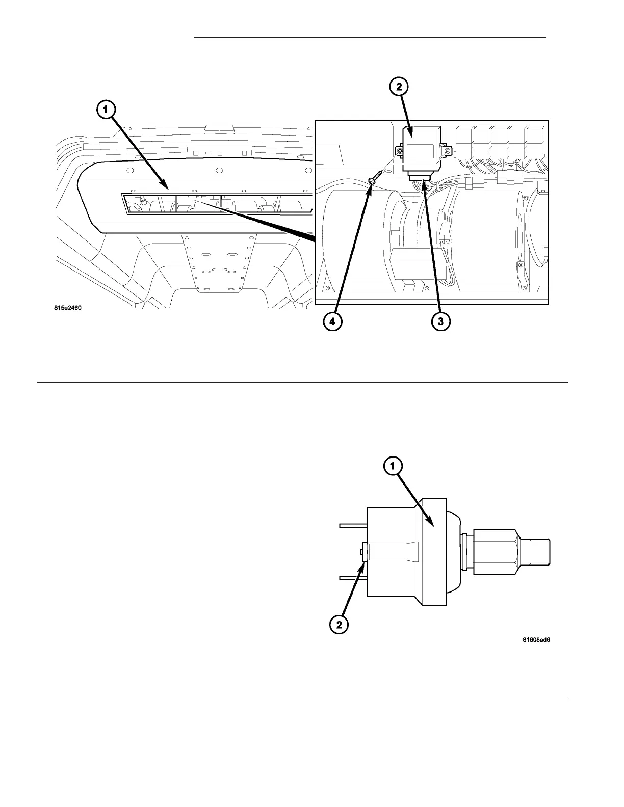
Fig. 6 Rear A/C Control Module
1 - REAR A/C EVAPORATOR HOUSING
2 - REAR A/C CONTROL MODULE
3 - WIRE HARNESS CONNECTOR
4 - SCREW (2)
Fig. 7 Rear A/C High Pressure Switch
1 - REAR PRESSURE SWITCH
2 - WIRE CONNECTOR
24 - 30 CON T R OL S - R EAR VA