rear A/C compressor operat ion when the rear dis-
charge line pressur e approaches h igh levels, and also
reduces electr ical su rging from rear A/C clutch
en ga gem en t .
The rear A/C high pressur e swit ch con trols rea r
A/C con denser cooling fan oper ation by mon itor ing
the rear dischar ge line pressure. When the rea r dis-
charge pr essu re rises above approxima tely 1900 to
2200 kPa (280 to 320 psi) the rear A/C condenser
coolin g fan will tu rn on . The rea r conden ser cooling
fan will tur n off wh en the rea r dischar ge pr essu re
dr ops t o approxima tely 1600 kPa (235 psi).
The rear A/C high pressur e switch cont acts open
when t he rear disch arge line pressure rises above
approximately 3100 to 3375 kPa (450 to 490 psi). The
rear A/C high pressure switch cont acts close when
the rea r discha rge line pressure drops t o a pproxi-
mately 1860 to 2275 kPa (270 to 330 psi).
The rear A/C high pr essu re switch is factory-cali-
brat ed a nd cann ot be a djust ed or repa ired an d, if
faulty or damaged, it mu st be repla ced. Refer to th e
appropriate wir ing informat ion for com plete HVAC
wir in g dia gr a m s.
REMOVAL
WARNING: Refer to the applicable warnings and
cautions for this system before performing the fol-
lowing operation (Refer to 24 - HEATING & AIR
CONDITIONING/PLUMBING - WARNINGS) and (Refer
to 24 - HEATING & AIR CONDITIONING/PLUMBING -
CAUTIONS). Failure to follow the warnings and cau-
tions could result in possible personal injury or
death.
(1) Disconn ect and isolate the negat ive ba tter y
cable.
(2) Remove th e air filter from the rea r A/C evapo-
rator hou sing (Refer t o 24 - H EATING & AIR CON-
DITIONING/DISTRIBUTION - REAR/AIR F ILTER -
REMOVAL).
(3) Recover the refr iger ant from the rear r efriger-
ant system (Refer to 24 - HEATING & AIR CONDI-
TIONING/PLUMBING - STANDARD PROCEDURE -
REFRIGERANT RECOVERY).
(4) Remove the cover from the r ear A/C condenser
housin g (Refer to 24 - H EATING & AIR CONDI-
TIONING/DISTRIBUTION - REAR/A/C CON-
DENSER COVE R - REMOVAL).
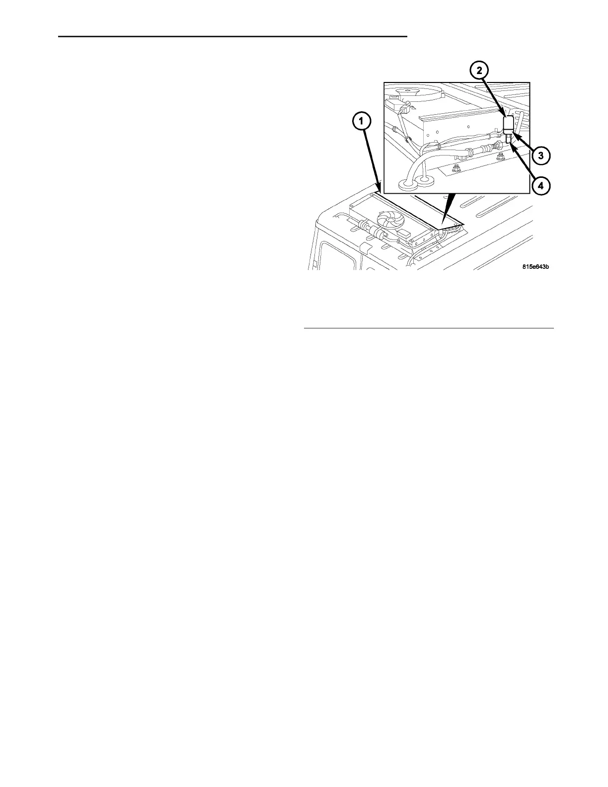
(5) Disconn ect the wire ha rness connector from th e
rear A/C high pressur e switch (Fig. 8).
(6) Remove t he rea r A/C high pressure switch and
insta ll a plug into, or tape over the opened rear dis-
charge line fitting.
INSTALLATION
NOTE: Replacement of the PTFE thread sealing
tape is required anytime the rear A/C high pressure
switch is removed from the rear discharge line. Fail-
ure to replace the sealing tape could result in a rear
refrigerant system leak.
(1) Remove the tape or plug from the rear dis-
charge line fitting.
(2) In st all PTF E t hrea d sealing t ape on to the rear
A/C high pressure switch and insta ll the swit ch on to
the rea r discharge line. Tigh tened th e A/C high pres-
su re switch to 10 N·m (88 in. lbs.).
(3) Connect the wir ing ha rness con nector to t he
rear A/C high pressur e switch.
(4) Reconnect t he negat ive batt ery cable.
(5) Eva cuate th e rear refr iger ant system (Refer to
24 - HEATING & AIR CONDITIONING/P LUMBING
- STANDARD PROCEDURE - REFRIGERANT SYS-
TEM EVACUATE).
(6) Char ge the r ear refr igerant syst em (Refer to 24
- HEATING & AIR CONDITIONING/P LUMBING -
STANDARD PROCEDURE - REFRIGE RANT SYS-
TEM CH ARGE).
(7) In st all th e rea r air filter (Refer to 24 - HEAT-
ING & AIR CONDITIONING/DISTRIBUTION -
REAR/AIR FILTE R - INSTALLATION).
(8) In st all t he cover onto the rea r A/C conden ser
housin g (Refer to 24 - H EATING & AIR CONDI-
TIONING/DISTRIBUTION - REAR/A/C CON-
DENSER COVE R - INSTALLATION).
Fig. 8 Rear A/C High Pressure Switch
1 - REAR A/C CONDENSER
2 - WIRE HARNESS CONNECTOR
3 - REAR A/C HIGH PRESSURE SWITCH
4 - REAR DISCHARGE LINE FITTING
VA CONTROLS - REAR 24 - 31