A/CLOWPRESSURESWITCH
DESCRIPTION
The rear A/C low pr essu re switch provides a sign al
to the rear A/C control module t o regu lat e the r ear
refriger ant system pressure and cont rol r ear A/C
evapor ator t empera ture (Fig. 9). The rear A/C contr ol
module will disen gage the rear A/C clut ch if th e rear
refriger ant system suction line pressure falls below
30 kPa (4.4 psi).
The rear A/C low pr essu re swit ch is m ounted on a
fitting located on the r ear suction line near th e left
side of the rea r A/C evaporator housing.
The rear refrigera nt system must be dischar ge
pr ior t o rem ovin g the r ear A/C low pressur e swit ch.
OPERATION
The rear A/C low pressure switch is electrically
connect ed in ser ies with the rea r A/C high pressur e
switch , between groun d and the rea r A/C control
module.
The rear A/C low pressure switch cont act opens or
closes th e pa th t he grou nd, signaling th e r ear A/C
control module to tu rn t he rear A/C clut ch on and off.
This r egulates the rear refrigerant system pressur e
and con trols rea r A/C evaporator t empera ture. Con-
trollin g the rea r evaporator tempera ture prevents
condensate water on th e evapor ator fins from freez-
ing and obstructing rear A/C system a ir flow.
The rear A/C low pr essu re switch conta cts are open
when th e rear suction line pressure is approximately
152 kPa (22 psi) or lower. The rear A/C low pr essu re
switch conta cts will close when the rear su ction line
pr essu re rises t o approximately 234 to 262 kPa (34 to
38 psi) or above. Lower a mbient tem per atu res, below
approximately -1° C (30° F), will also cause th e rea r
A/C low pressure switch cont acts to open du e to the
pr essu re/tempera ture r elat ionship of the r efrigera nt
in the s ys te m.
The rear A/C low pressur e switch is fa ctory-cali-
brat ed a nd cann ot be a djust ed or repa ired an d, if
faulty or damaged, it mu st be repla ced. Refer to th e
appropriate wir ing informat ion for com plete HVAC
wir in g dia gr a m s.
REMOVAL
WARNING: Refer to the applicable warnings and
cautions for this system before performing the fol-
lowing operation (Refer to 24 - HEATING & AIR
CONDITIONING/PLUMBING - WARNINGS) and (Refer
to 24 - HEATING & AIR CONDITIONING/PLUMBING -
CAUTIONS). Failure to follow the warnings and cau-
tions could result in possible personal injury or
death.
(1) Disconn ect and isolate the negat ive ba tter y
cable.
(2) Remove th e cover from the rea r A/C evapor ator
housin g (Refer to 24 - H EATING & AIR CONDI-
TIONING/DISTRIBUTION - REAR/A/C EVAPORA-
TOR COVE R-REAR - RE MOVAL).
(3) Recover the refr iger ant from the rear r efriger-
ant system (Refer to 24 - HEATING & AIR CONDI-
TIONING/PLUMBING - STANDARD PROCEDURE -
REFRIGERANT RECOVERY).
(4) Remove the in su lat ing tape from around the
area of the r ear A/C low pressu re swit ch (Fig. 10).
(5) Disconn ect the wire ha rness connector from th e
rear A/C low pr essu re switch.
(6) Remove the rear A/C low pressur e switch a nd
insta ll a plug into, or tape over the opened rea r suc-
tion line fitt ing.
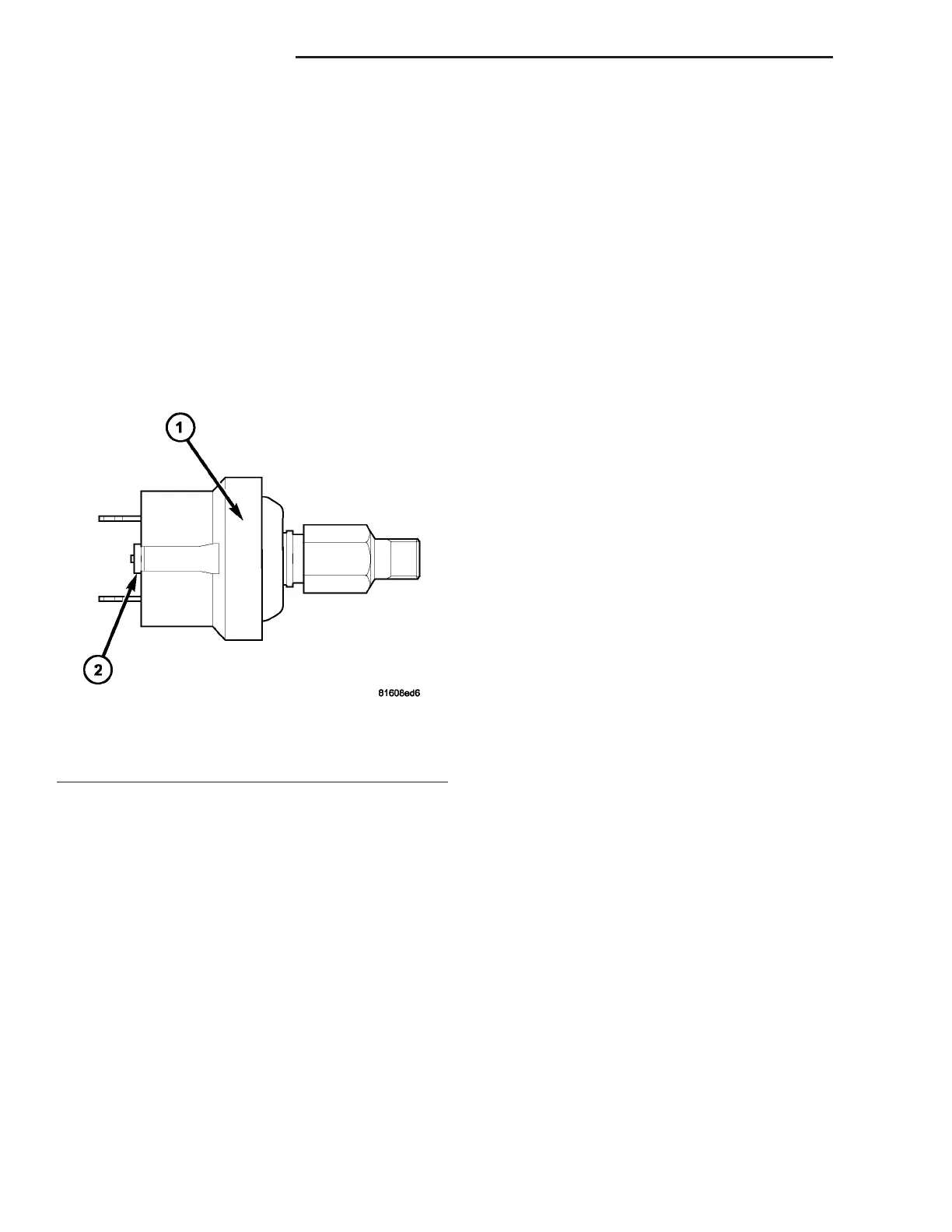
Fig. 9 Rear A/C Low Pressure Switch
1 - REAR PRESSURE SWITCH
2 - WIRE CONNECTOR
24 - 32 CON T R OL S - R EAR VA