INSTALLATION
NOTE: Replacement of the PTFE thread sealing
tape is required anytime the rear A/C low pressure
switch is removed from the rear suction line line.
Failure to replace the sealing tape could result in a
rear refrigerant system leak.
(1) Remove the tape or plug from th e rear suction
lin e fitt ing.
(2) In st all PTF E t hrea d sealing t ape on to the rear
A/C low pr essu re switch and insta ll th e switch on to
the rear suction line. Tight ened t he A/C low pr essu re
switch to 10 N·m (88 in . lbs.).
(3) Connect the wir ing ha rness con nector to t he
rear A/C low pr essu re switch.
(4) In st all n ew insulating t ape around the rea r A/C
low pressu re swit ch area .
(5) Reconnect t he negat ive batt ery cable.
(6) Eva cuate th e rear refr iger ant system (Refer to
24 - HEATING & AIR CONDITIONING/P LUMBING
- STANDARD PROCEDURE - REFRIGERANT SYS-
TEM EVACUATE).
(7) Char ge the r ear refr igerant syst em (Refer to 24
- HEATING & AIR CONDITIONING/P LUMBING -
STANDARD PROCEDURE - REFRIGE RANT SYS-
TEM CH ARGE).
(8) In st all the cover onto the rear A/C evaporator
housin g (Refer to 24 - H EATING & AIR CONDI-
TIONING/DISTRIBUTION - REAR/A/C EVAPORA-
TOR COVE R-REAR - INSTALLATION).
BLOWER M OT OR RELAY
DESCRIPTION
The th ree rea r blower motor relays u sed for th e
rear A/C system a re Inter nat ional St andards Organi-
zat ion (ISO)-t ype relays (Fig. 1 1). Relays conform ing
to the ISO specifications have com mon ph ysical
dimen sions, curr ent capacities, termina l fu nction s
and pat tern s. The rear blower motor relays are elec-
tromech anical devices tha t switches fused batt ery
curren t directly to the rear blower motors. The rear
blower motor relays are ener gized when the relay
coils are provided batt ery cur rent by the rear blower
motor switch (Refer to 24 - H EATING & AIR CON-
DITIONING/CONTROLS/BLOWE R MOTOR
SWITCH - DE SCRIP TION).
The rear blower motor rela ys are loca ted in th e
rela y block in the rear A/C eva por ator hou sing.
OPERATION
The t hree ISO-standard rear blower mot or relays
are electrom echan ical switches th at u ses a low cur-
rent input from t he r ear blower mot or switch t o con-
trol the h igh current ou tput to th e rear blower
motors. The movable, common feed relay conta ct is
held against the fixed, n orma lly closed relay contact
by spring pressu re. Wh en t he elect romagnetic relay
coil is energized, it draws the movable common feed
rela y contact a way fr om th e fixed, n ormally closed
rela y contact an d, h olds it aga inst the fixed, n ormally
open relay contact . Th is action allows high cur rent to
flow to the r ear blower motors.
When the relay coil is de-en ergized, spring pres-
su re ret urns t he movable relay contact back a gainst
the fixed, n orma lly closed cont act point. The resistor
Fig. 10 Rear A/C Low Pressure Switch
1 - INSULATING TAPE
2 - REAR A/C EVAPORATOR HOUSING
3 - WIRE HARNESS CONNECTOR
4 - REAR A/C LOW PRESSURE SWITCH
5 - REAR SUCTION LINE FITTING
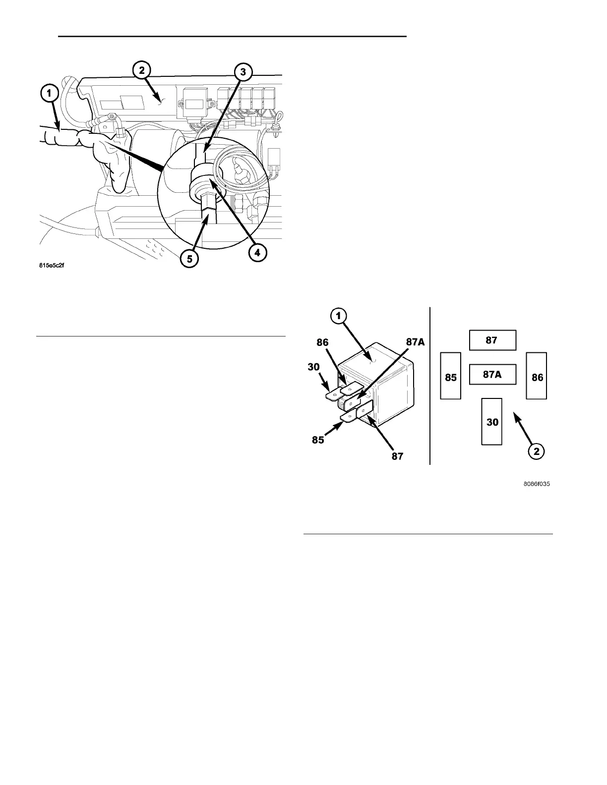
Fig. 11 Rear Blower Motor Relays
1 - STANDARD ISO RELAY
2 - TERMINAL PATTERN
VA CONTROLS - REAR 24 - 33