BLOWER M OT OR
REMOVAL
(1) Disconn ect and isolate the negat ive ba tter y
cable.
(2) Remove th e engine air clean er housing cover
(Refer to 9 - ENGINE/AIR INTAKE SYSTEM/AIR
CLEANER E LEMENT - REMOVAL).
(3) Position the vent ilation housing insulation
blan ket out of the wa y of the blower mot or a ssem bly.
(4) Disconn ect the wire ha rness connector from th e
blower m otor (Fig. 4).
(5) Remove the thr ee blower motor retainin g
scr ews.
(6) Remove th e blower motor assembly fr om th e
vent ila tion hou sing.
INSTALLATION
(1) In st all the blower motor assembly into the ven-
tilation housing.
(2) In st all the thr ee blower motor r etaining
scr ews. Tighten t he screws to 2 N·m (17 in. lbs.).
(3) Connect th e wire harness con nector to the
blower m otor.
(4) In st all th e ventilat ion housing insulation blan-
ket.
(5) In st all th e engine air cleaner cover (Refer to 9 -
ENGINE/AIR INTAKE SYSTE M/AIR CLEANE R
HOUSING - INSTALLATION).
(6) Reconnect t he negat ive batt ery cable.
DEFROST ER DU CT S
REMOVAL
(1) Remove t he instrument pan el (Refer to 23 -
BODY/INSTRUMENT PANEL - REMOVAL).
(2) Remove the screw th at secu res the left an d/or
right side defroster duct t o the heater hou sing,
depending on the duct being r emoved (Fig. 5).
(3) Remove the defroster duct(s) from the hous-
ing.
INSTALLATION
(1) In st all the left and/or right side defroster duct
on to th e heater housing.
(2) In st all th e screw th at secur es the defr ost er
du ct to th e housing. Tighten th e screw(s) to 2 N·m
(17 in . lbs.).
(3) In st all th e in st rument pan el (Refer to 23 -
BODY/INSTRUMENT PANEL - INSTALLATION).
FLOOR DI ST RI BU T I ON DU CT S
REMOVAL
(1) Remove t he instrument pan el (Refer to 23 -
BODY/INSTRUMENT PANE L/INSTRUMENT
PANEL ASSEMBLY - REMOVAL).
(2) Remove the defroster ducts (Refer to 24 -
HEATING & AIR CONDITIONING/DISTRIBUTION/
DEFROSTER DUCTS - REMOVAL).
(3) Remove t he scr ews th at secur e the left a nd
right floor distribution ducts to th e instr umen t pa nel
su pport (Fig. 6).
(4) Remove floor distribut ion duct s from th e center
floor distr ibut ion duct.
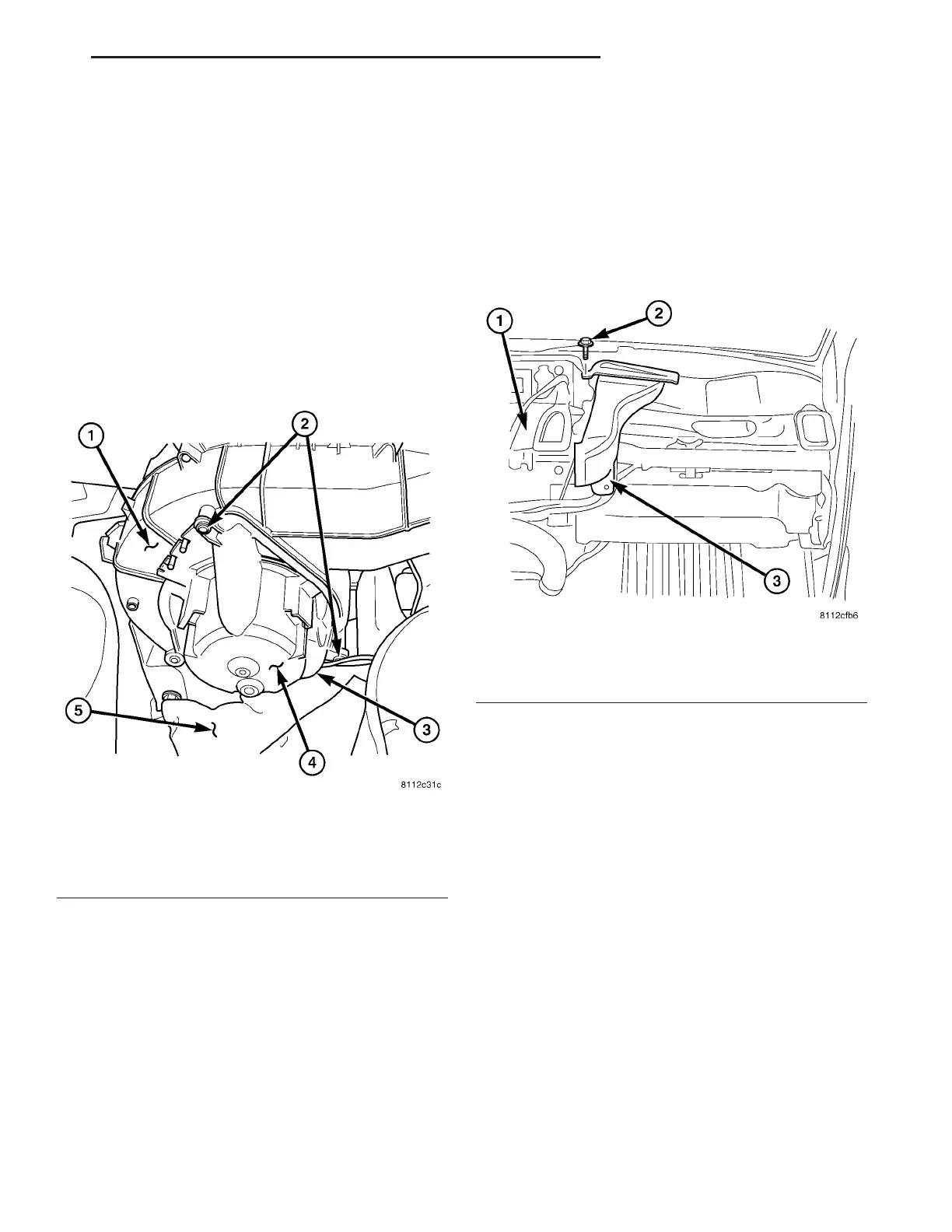
Fig. 4 Blower Motor Assembly
1 - VENTILATION HOUSING
2 - SCREWS (3)
3 - WIRE HARNESS CONNECTOR
4 - BLOWER MOTOR
5 - INSULATION BLANKET
Fig. 5 Defroster Duct - RH Shown, LH Typical
1 - HEATER HOUSING
2 - SCREW
3 - DEFROSTER DUCT
VA DISTRIBUTION - FRONT 24 - 47