(4) If servicing the passen ger side air ou tlet s,
remove th e passenger side air nozzle reinforcing
plate scr ews and the reinforcing plate (Fig. 2).
(5) If servicing the passen ger side air ou tlet s,
remove t he passenger side air nozzle a ssembly u sing
a t rim stick or other suitable wide flat bla de t ool,
until the snap featu res on the nozzle assembly ar e
released.
(6) If servicing the passen ger side air ou tlet s,
remove th e air outlet retaining bracket from the
right side of the instr umen t panel (F ig. 3).
(7) Remove the instrument pan el end cover screws
and the left a nd/or right side cover.
(8) Remove the air outlet retaining screws and th e
air outlets a s r equired.
INSTALLATION
(1) In st all the air outlets and retaining screws as
required. Tighten the screws to 2 N·m (17 in. lbs.).
(2) In st all the left and/or right side instr umen t
pa nel en d cover and retainin g screws a s requir ed.
Tighten t he screws to 2 N·m (17 in. lbs.).
(3) If servicing the passen ger side air ou tlet s,
insta ll t he air outlet retainin g bracket to the right
side of t he instr umen t pa nel. Tighten the screw to 2
N·m (17 in. lbs.).
(4) If servicing the passen ger side air ou tlet s,
insta ll the pa ssen ger side air nozzle a ssem bly by
pr essing th e nozzle assembly firmly a nd evenly into
the instr umen t pan el, until th e sn ap features are
fully en gaged.
(5) If servicing the passen ger side air ou tlet s,
insta ll the pa ssen ger side air nozzle reinfor cing plate
and reta ining screws. Tighten t he scr ews to 2 N·m
(17 in . lbs.).
(6) If servicing the passen ger side air ou tlet s,
insta ll the passen ger side air bag (Refer t o8-ELEC-
TRICAL/RESTRAINTS/PASSE NGE R AIRBAG -
INSTALLATION).
(7) If servicing the driver side air outlets, insta ll
the instr umen t cluster bezel (Refer to 23 - BODY/IN-
STRUME NT PANE L/CLUSTER BE ZEL - INSTAL-
LATION).
(8) Reconnect t he battery negative cable.
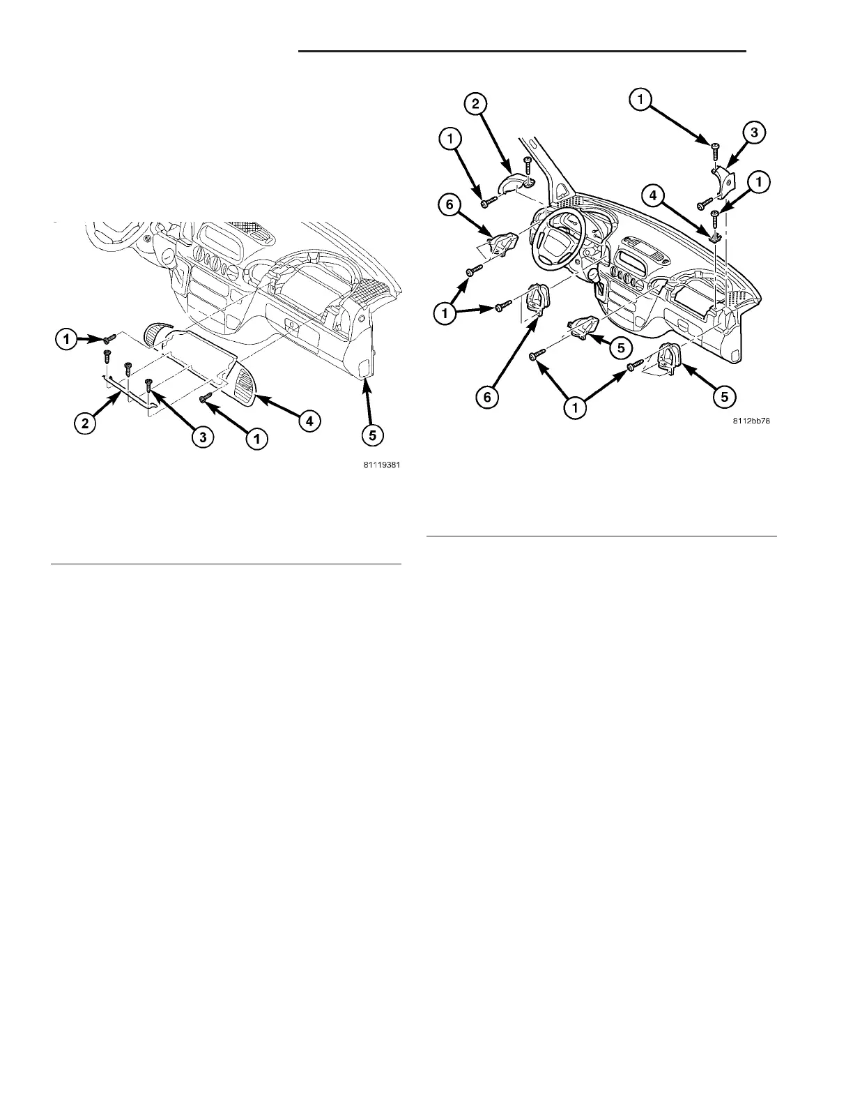
Fig. 2 Passenger Side Air Nozzle Cover
1 - FRONT SCREWS (2)
2 - BRACKET
3 - BRACKET SCREWS
4 - NOZZLE COVER
5 - INSTRUMENT PANEL
Fig. 3 Instrument Panel Air Outlets
1 - SCREW (15)
2 - LH END COVER
3 - RH END COVER
4 - BRACKET
5 - PASSENGER SIDE AIR OUTLET (2)
6 - DRIVER SIDE AIR OUTLET (2)
24 - 46 DISTRIBUTION - FRONT VA