DI ST RI BU T I ON - FRON T
TABLE OF CONTENTS
page page
AIR FILTER
REMOVAL . . . . . . . . . . . . . . . . . . . . . . . . . . . . . 45
INSTALLATION . . . . . . . . . . . . . . . . . . . . . . . . . 45
AIR OUTLETS
REMOVAL . . . . . . . . . . . . . . . . . . . . . . . . . . . . . 45
INSTALLATION . . . . . . . . . . . . . . . . . . . . . . . . . 46
BLOWER MOTOR
REMOVAL . . . . . . . . . . . . . . . . . . . . . . . . . . . . . 47
INSTALLATION . . . . . . . . . . . . . . . . . . . . . . . . . 47
DEFROSTER DUCTS
REMOVAL . . . . . . . . . . . . . . . . . . . . . . . . . . . . . 47
INSTALLATION . . . . . . . . . . . . . . . . . . . . . . . . . 47
FLOOR DISTRIBUTION DUCTS
REMOVAL . . . . . . . . . . . . . . . . . . . . . . . . . . . . . 47
INSTALLATION . . . . . . . . . . . . . . . . . . . . . . . . . 48
HVAC HOUSING
REMOVAL . . . . . . . . . . . . . . . . . . . . . . . . . . . . . 48
DISASSEMBLY . . . . . . . . . . . . . . . . . . . . . . . . . 49
ASSEMBLY . . . . . . . . . . . . . . . . . . . . . . . . . . . . 50
INSTALLATION . . . . . . . . . . . . . . . . . . . . . . . . . 50
INSTRUMENT PANEL DUCTS
REMOVAL . . . . . . . . . . . . . . . . . . . . . . . . . . . . . 51
INSTALLATION . . . . . . . . . . . . . . . . . . . . . . . . . 51
AI R FI LT ER
REMOVAL
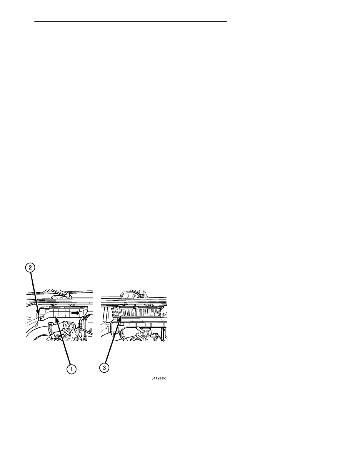
(1) Remove t he insulation blanket from the vent i-
lat ion housing in the engine compart ment (F ig. 1).
(2) Open the locking clips at the fr ont an d rea r of
the vent ila tion hou sing.
(3) Slide the ventilation housing cover in the dir ec-
tion of t he ar row shown.
(4) Remove the air filter.
INSTALLATION
(1) In st all the air filter into th e ventilat ion hou s-
ing.
(2) In st all the ventilation housing cover
(3) Close the lockin g clips at t he fron t and rea r of
the vent ila tion hou sing.
NOTE: The locking tabs should retain the ventila-
tion housing cover securely.
(4) In st all t he in su lation blan ket onto th e vent ila -
tion housing.
AI R OU T LET S
REMOVAL
WARNING: To avoid personal injury or death, on
vehicles equipped with airbags, disable the supple-
mental restraint system before attempting any
steering wheel, steering column, airbag, seat belt
tensioner, impact sensor, or instrument panel com-
ponent diagnosis or service. Disconnect and isolate
the battery negative (ground) cable, then wait two
minutes for the system capacitor to discharge
before performing further diagnosis or service. This
is the only sure way to disable the supplemental
restraint system. Failure to take the proper precau-
tions could result in accidental airbag deployment.
(1) Disconn ect and isolate the battery nega tive
cable.
(2) If servicing th e driver side air ou tlet s, remove
the instr umen t cluster bezel (Refer to 23 - BODY/IN-
STRUME NT PANEL/CLUSTER BE ZEL -
REMOVAL).
(3) If servicing the passen ger side air ou tlet s,
remove the passenger side airba g (Refer to8-ELEC-
TRICAL/RESTRAINTS/PASSE NGE R AIRBAG -
REMOVAL).
Fig. 1 Air Filter Element
1 - VENTILATION HOUSING INSULATION BLANKET
2 - LOCKING CLIP (2)
3 - AIR FILTER
VA DISTRIBUTION - FRONT 24 - 45