(11) Disconn ect t he heater hoses from the hea ter
core.
(12) Disconn ect the hea ter hoses from t he heater
core t ubes. Install plugs in, or ta pe over th e opened
heat er core tubes.
(13) Remove the two bolts secur ing the refriger ant
lin es to the evapora tor tubes and discon nect the lines
from the t ubes. Insta ll plugs in, or tape over all of
the opened refr igeran t line fitt ings.
(14) Remove t he sea ls from the refr iger ant line fit-
tings and discard.
(15) Install plugs in, or tape over the opened
refriger ant line fitt ings and evapora tor tubes.
(16) Remove the instrumen t pan el from the vehicle
(Refer to 23 - BODY/INSTRUMENT PANE L -
REMOVAL).
(17) Remove the defroster, floor distr ibut ion a nd
instr umen t panel ducts (Refer to 24 - HE ATING &
AIR CONDITIONING/DISTRIBUTION/DEFROSTER
DUCTS - REMOVAL), (Refer t o 24 - HE ATING &
AIR CONDITIONING/DISTRIBUTION/F LOOR DIS-
TRIBUTION DUCTS - RE MOVAL) an d (Refer to 24 -
HEATING & AIR CONDITIONING/DISTRIBUTION/
INSTRUMENT PANEL DUCTS - RE MOVAL).
(18) Disconn ect t he two bulkhead groun d connec-
tions n ear in strument cluster a rea.
(19) Remove the passenger a irbag br acket (Refer
to 8 - ELECTRICAL/RESTRAINTS/PASSE NGER
AIRBAG - REMOVAL).
(20) Disconn ect the wire har ness connector from
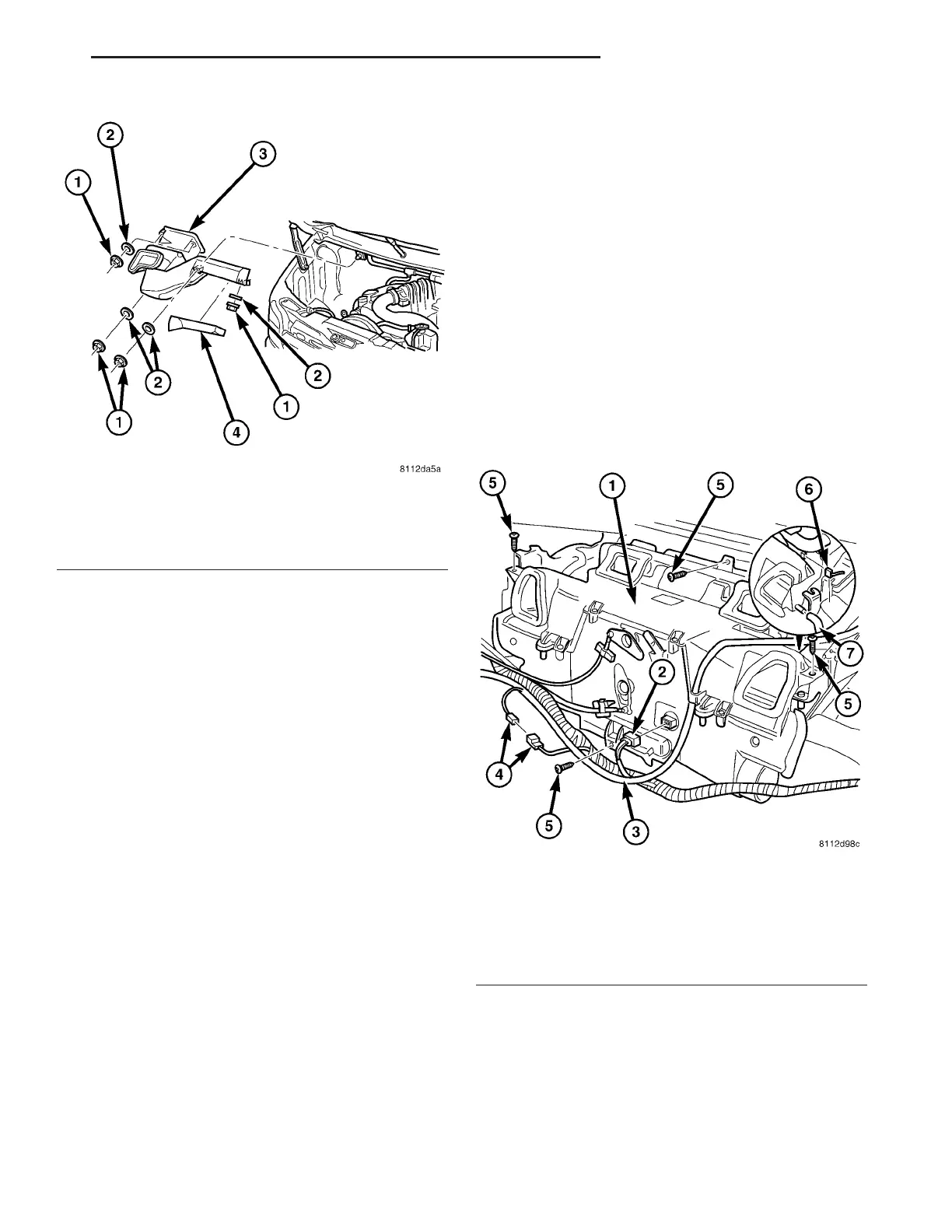
the evaporator tem per atu re sensor an d a ir ou tlet
temper ature sensor (Fig. 8).
(21) Remove the wir e h arness from th e br acket
locat ed on t he right side of t he heat er housing a nd
position t he wire harness ou t of the way.
(22) Disconn ect the A/C-heater control cables from
the mode door levers (Refer t o 24 - HEATING & AIR
CONDITIONING/CONTROLS/MODE DOOR CABLE
- REMOVAL).
(23) Disconn ect the evaporator dr ain tu be from the
HVAC housin g.
(24) Remove t he five bolts secu rin g the H VAC
housin g to the body.
NOTE: Make sure that the interior is protected in
case of loss of residual fluids from the heater core
and the A/C evaporator.
(25) Remove th e H VAC housing from the vehicle.
DISASSEMBLY
(1) Remove the H VAC housing fr om the veh icle
(Refer to 24 - HE ATING & AIR CONDITIONING/
DISTRIBUTION/HVAC HOUSING - REMOVAL).
(2) Pla ce t he HVAC housing in the upright position
on a work bench, making a llowa nce for leakage of
fluids.
Fig. 7 Ventilation Housing
1 - NUT (5)
2 - WASHER (5)
3 - VENTILATION HOUSING
4 - HOUSING COVER
Fig. 8 Heater Housing
1 - HEATER HOUSING
2 - AIR TEMP SENSOR WIRE CONNECTOR
3 - WIRE HARNESS
4 - WIRE HARNESS CONNECTOR
5 - BOLT (4)
6 - EVAP TEMP SENSOR WIRE CONNECTOR
7 - EVAPORATOR DRAIN TUBE
VA DISTRIBUTION - FRONT 24 - 49