(3) Remove t he gasket locat ed a t t he A/C eva pora-
tor and heater core tu bes a nd the gasket that seals
the ventilat ion housing to the HVAC hou sing (Fig. 9).
(4) Remove t he 12 screws tha t secur e t he two
housin g ha lves toget her.
(5) Seperat e the two h ousing ha lves.
(6) Remove t he heater core from the lower h ous-
ing.
(7) Remove the wire har ness.
(8) Remove the three heat er core tube ret ain ing
bolts a nd th e heater core tube assembly from th e
heat er core.
(9) Remove the hea ter core tu be seals and discar d.
(10) Install plu g in , or t ape over the opened hea ter
core fittings.
(11) Remove the A/C eva porator from th e lower
housin g.
ASSEMBLY
(1) In st all t he A/C evaporator into th e lower hous-
ing.
(2) Remove t he tape or plugs fr om t he hea ter core
fittings.
(3) Lubricate two new r ubber O-ring sea ls with
clean en gin e coolant and install t hem onto th e heater
core fitting.
(4) Connect the hea ter core t ube assem bly to the
heat er cor e and inst all the th ree ret ain ing bolts.
Tighten t he bolts to 5 N·m (45 in. lbs.).
(5) In st all the wire har ness.
(6) In st all the heater core into the lower housing.
(7) In st all the two h ousing ha lves t ogeth er.
(8) In st all the 12 screws t hat secu re the t wo h ous-
ing halves togeth er. Tighten t he scr ews to 2 N·m (17
in. lbs.).
(9) In st all th e gasket for the A/C evapor ator and
heat er core tu be out lets and t he gasket that seals t he
vent ila tion hou sing to t he HVAC h ousing.
(10) Install the HVAC hou sing (Refer to 24 -
HEATING & AIR CONDITIONING/DISTRIBUTION/
HVAC HOUSING - INSTALLATION).
INSTALLATION
NOTE: High pressures are produced in the refriger-
ant system when the A/C compressor is operating.
Extreme care must be exercised to make sure that
each of the refrigerant system connections is pres-
sure-tight and leak free.
(1) Position the HVAC hou sing t o th e da sh pa nel.
Be cer tain th at t he evapor ator condensa te drain tube
is positioned correctly.
(2) In st all th e screws that secur e th e HVAC hous-
ing to the dash pa nel. Tigh ten the screws to 4.5 N·m
(40 in . lbs.).
(3) Connect the HVAC housing wire h arness con-
nector s a nd insta ll the wirin g harness to the bracket.
(4) Connect the A/C-hea ter control cables to the
mode door levers (Refer to 24 - HEATING & AIR
CONDITIONING/CONTROLS/MODE DOOR CABLE
- INSTALLATION).
(5) Reinstall t he passenger airbag bracket (Refer
to 8 - ELECTRICAL/RESTRAINTS/PASSE NGER
AIRBAG - INSTALLATION).
(6) Reconnect the two bu lkhead ground con nection
near t he in st rumen t cluster area .
(7) Reinstall th e defrost er, floor distribution and
instr umen t pa nel du cts.
(8) Reinstall the instrumen t pa nel (Refer to 23 -
BODY/INSTRUMENT PANE L/INSTRUMENT
PANEL ASSEMBLY - INSTALLATION).
(9) Unplug or remove the tape from the opened
refriger ant line fitt ings.
(10) Lubr icate two n ew r ubber O-ring seals with
clean refr igerant oil and install t hem onto the evap-
orator core fittings.
(11) Connect the refriger ant line ter mina l block to
the evapor ator tu bes.
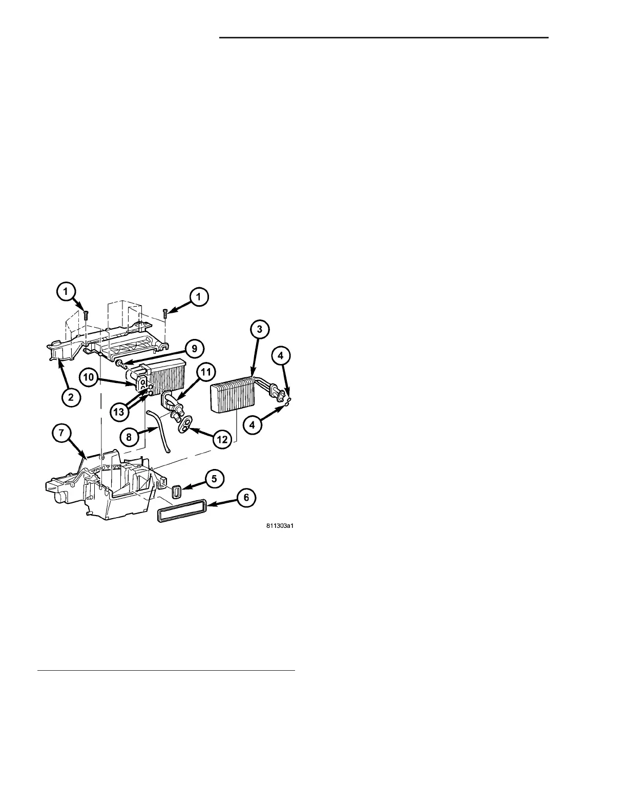
Fig. 9 HVAC Housing
1 - SCREW (12)
2 - UPPER HOUSING
3 - A/C EVAPORATOR
4 - EVAPORATOR O-RING SEAL (2)
5 - EVAPORATOR GASKET
6 - VENTILATION HOUSING GASKET
7 - LOWER HOUSING
8 - WIRING HARNESS
9 - BOLT (3)
10 - HEATER CORE
11 - HEATER CORE TUBE ASSEMBLY
12 - HEATER CORE TUBE GASKET
13 - HEATER CORE TUBE O-RING SEAL (2)
24 - 50 DISTRIBUTION - FRONT VA