(12) Install the two bolt s that secure the refriger-
ant line term inal block t o t he A/C evapor ator.
Tighten t he bolts to 5 N·m (45 in. lbs.).
(13) Un plug or rem ove the tape from t he heater
core hoses a nd tubes.
(14) Connect the hea ter hoses to the heat er core
tubes and install the hea ter hose clamps.
(15) Install the vent ila tion hou sing to th e dash
panel.
(16) Install the nuts and washer s th at secu re the
vent ila tion housing to the dash panel. Tigh ten th e
nuts to 5 N·m (45 in . lbs.).
(17) Connect t he wire ha rness conn ectors to the
blower m otor, blower mot or resistor block and the
recir cula tion door actuator.
(18) Connect th e vacu um harness con nector to t he
recir cula tion door actuator.
(19) Install the a ir filter into th e ventilat ion hous-
ing (Refer to 24 - HEATING & AIR CONDITION-
ING/DISTRIBUTION/AIR FILTER -
INSTALLATION).
(20) Install th e windshield wa sh er reser voir (Refer
to 8 - ELECTRICAL/WIPERS/WASHERS/WASHER
RESERVOIR - INSTALLATION).
(21) Install the air clean er housing (Refer to 9 -
ENGINE/AIR INTAKE SYSTE M/AIR CLEANE R
HOUSING - INSTALLATION).
(22) Reconn ect the n egative battery cable.
(23) If the h eater core is being r eplaced, flu sh the
coolin g system (Refer t o 7 - COOLING - STANDARD
PROCE DURE - COOLING SYSTEM CLEANING/
REVERSE FLUSHING).
(24) Refill the engine cooling system (Refer to 7 -
COOLING/ENGINE/COOLANT - STANDARD PRO-
CEDURE - COOLANT SYSTEM F ILL).
(25) Eva cuat e the refr iger ant system (Refer to 24 -
HEATING & AIR CONDITIONING/PLUMBING -
STANDARD PROCEDURE - REFRIGE RANT SYS-
TEM EVACUATE).
(26) Charge th e refrigerant system (Refer to 24 -
HEATING & AIR CONDITIONING/PLUMBING -
STANDARD PROCEDURE - REFRIGE RANT SYS-
TEM CH ARGE).
INSTRUMENT PANEL DUCTS
REMOVAL
(1) Remove t he instrument pan el (Refer to 23 -
BODY/INSTRUMENT PANE L/INSTRUMENT
PANEL ASSEMBLY - REMOVAL).
(2) Remove the defroster ducts (Refer to 24 -
HEATING & AIR CONDITIONING/DISTRIBUTION/
DEFROSTER DUCTS - REMOVAL).
(3) Remove th e floor distr ibut ion ducts (Refer to 24
- H EATING & AIR CONDITIONING/DISTRIBU-
TION/F LOOR DISTRIBUTION DUCTS -
REMOVAL).
(4) If rem ovin g the right instr umen t panel duct,
remove the pa ssen ger air bag modu le and br acket
(Refer to 8 - ELECTRICAL/RESTRAINTS/PASSEN-
GER AIRBAG - REMOVAL).
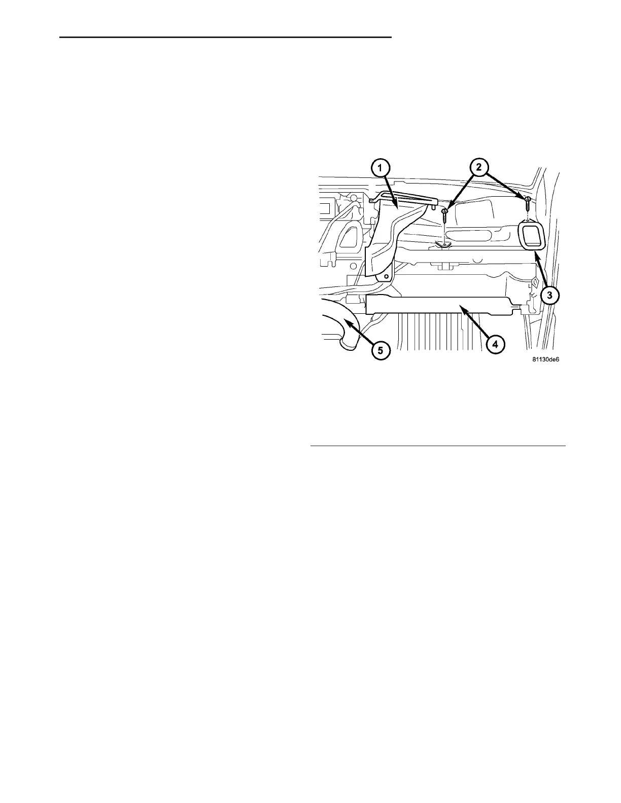
(5) Remove the screws tha t secu re the left a nd/or
right in st rumen t pa nel du ct and rem ove th e duct(s)
as requir ed (Fig. 10).
INSTALLATION
(1) Connect the instrument panel duct(s) t o t he
heat er housing a s required.
(2) In st all t he in st rumen t pa nel duct retaining
scr ews. Tighten t he screws to 2 N·m (17 in. lbs.).
(3) If servicing the right instr umen t panel duct ,
insta ll th e passen ger a ir ba g module a nd bracket
(Refer to 8 - ELECTRICAL/RESTRAINTS/PASSEN-
GER AIRBAG - INSTALLATION).
(4) In st all th e floor distr ibut ion ducts (Refer to 24
- H EATING & AIR CONDITIONING/DISTRIBU-
TION/F LOOR DISTRIBUTION DUCTS - INSTAL-
LATION).
(5) In st all th e defroster duct s (Refer t o 24 - H EAT-
ING & AIR CONDITIONING/DISTRIBUTION/DE-
FROSTER DUCTS - INSTALLATION).
(6) In st all th e in st rument pan el (Refer to 23 -
BODY/INSTRUMENT PANE L/INSTRUMENT
PANEL ASSEMBLY - INSTALLATION).
Fig. 10 Instrument Panel Duct - RH Shown, LH
Typical
1 - RH DEFROSTER DUCT
2 - SCREW (2)
3 - RH INSTRUMENT PANEL DUCT
4 - RH FLOOR DISTRIBUTION DUCT
5 - CENTER FLOOR DISTRIBUTION DUCT
VA DISTRIBUTION - FRONT 24 - 51