INSTALLATION
(1) Position t he r ear blower motor being serviced
to th e rea r A/C eva por ator housing.
(2) In st all the scr ews tha t secur e each r ear blower
motor to t he rear A/C evapora tor housing. Tigh ten
the scr ews to 5 N·m (45 in. lbs.).
(3) In st all a new bead of body sealant to t he
blower m otor area bein g serviced.
(4) In st all the rear blower mot or suppression filter
and con nect t he wiring ha rness connector s to the
su ppression filter and to the rear blower m otor being
serviced.
(5) In st all the cover onto the rear A/C evaporator
housin g (Refer to 24 - H EATING & AIR CONDI-
TIONING/DISTRIBUTION - REAR/A/C EVAPORA-
TOR COVE R-REAR - INSTALLATION).
(6) Reconnect t he negat ive batt ery cable.
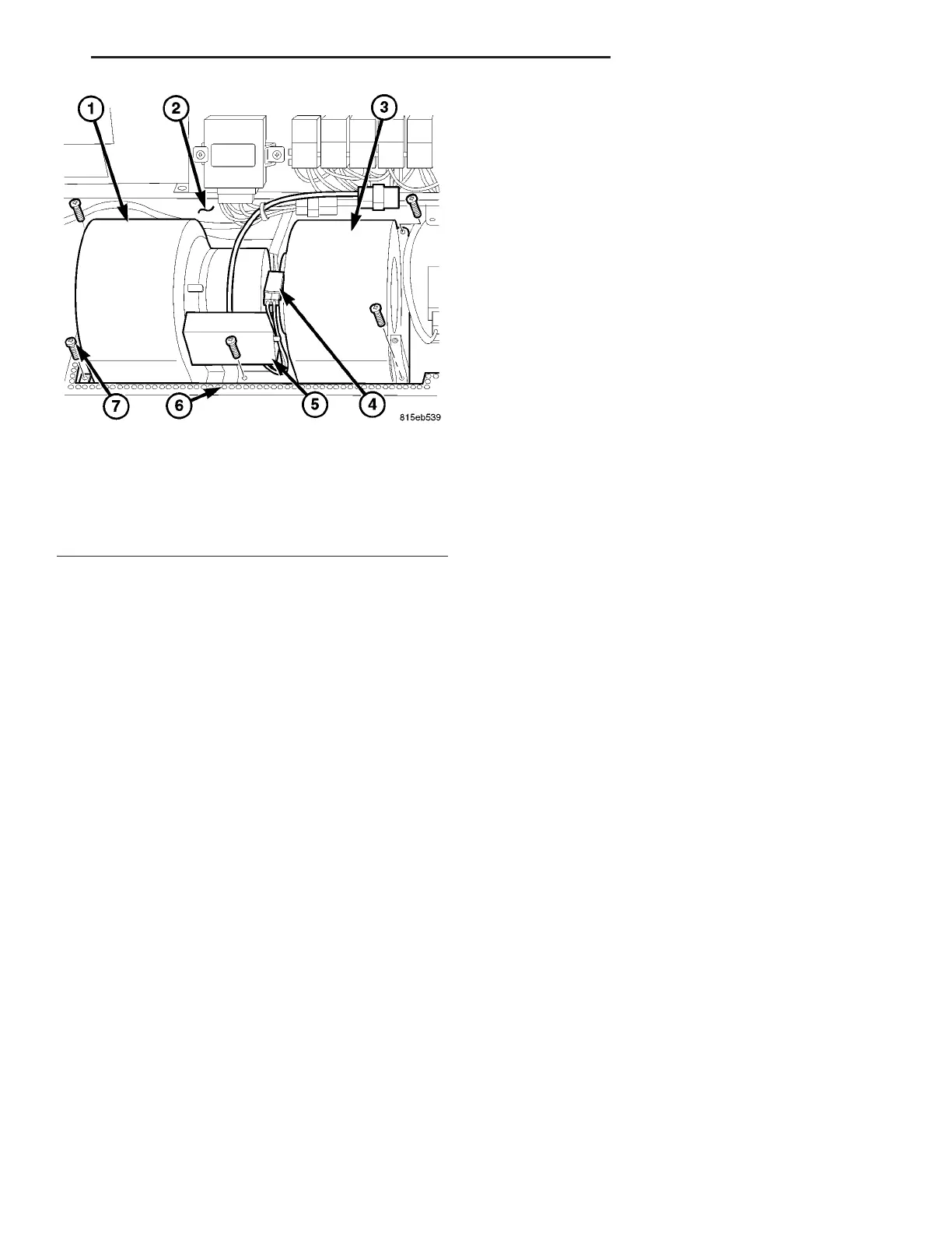
Fig. 7 Rear Blower Motors - LH shown, RH similar
1 - REAR BLOWER MOTOR (2)
2 - REAR A/C EVAPORATOR HOUSING
3 - SUPPRESSION FILTER WIRE CONNECTOR
4 - BLOWER MOTOR WIRE CONNECTOR
5 - REAR BLOWER MOTOR SUPPRESSION FILTER
6 - SEALER
7 - SCREW (5 PER MOTOR)
VA DISTRIBUTION - REAR 24 - 59