SYSTEM EMPTY
(1) Eva cuate th e r efrigera nt syst em t o the lowest
degree of vacuu m possible (approxima tely 28 in H g.)
(Refer to 24 - HE ATING & AIR CONDITIONING/
PLUMBING - STANDARD PROCEDURE - REFRIG-
ERANT SYSTEM EVACUATE ). Determine if the
system holds a va cuum for 15 min utes. If va cuum is
held, a leak is probably not present. If system will
not mainta in vacuum level, proceed to St ep 2.
(2) Prepa re and dispen se 0.284 kilogra ms (10
ounces) of R-134a refrigera nt into th e eva cuated
refriger ant system (Refer to 24 - HEATING & AIR
CONDITIONING/PLUMBING - STANDARD PRO-
CEDURE - REFRIGE RANT SYSTEM CHARGE) and
pr oceed to Step 1 of the System Low pr ocedure.
SYSTEM LOW
(1) Position the vehicle in a wind free wor k area .
This will aid in detectin g small leaks.
(2) Operat e the heating-A/C system with t he
engine at idle un der the following conditions for a t
least five m inutes.
• Door s or windows open
• Tra nsmission in Pa rk
• A/C-h eater contr ols set to outside air, full cool,
pa nel mode, high blower an d with A/C compressor
en ga ged
CAUTION: A leak detector only designed for R-12
refrigerant will not detect leaks in a R-134a refriger-
ant system.
(3) Sh ut the veh icle Off and wait 2-7 minut es.
Then use a n electron ic leak detector tha t is designed
to det ect R-134a refr igerant and sea rch for lea ks. Fit-
tings, lines or compon ents that appear to be oily usu-
ally indica te a refriger ant leak. To inspect t he A/C
evapor ator for leaks, insert the leak det ector pr obe
into th e drain t ube open ing or an air out let. A dye for
R-134a is ava ila ble to aid in lea k detection . Use only
Daim lerChrysler approved refr iger ant dye.
STAN DARD PROCEDU RE
REFRIGERANT SYSTEM SERVICE EQUIPMENT
WARNING: Eye protection must be worn when ser-
vicing an A/C refrigerant system. Turn off (rotate
clockwise) all valves on the equipment being used,
before connecting to or disconnecting from the
refrigerant system. Failure to observe these warn-
ings may result in possible personal injury.
WARNING: Refer to the applicable warnings and
cautions for this system before performing the fol-
lowing operation (Refer to 24 - HEATING & AIR
CONDITIONING/PLUMBING - WARNINGS) and (Refer
to 24 - HEATING & AIR CONDITIONING/PLUMBING -
CAUTIONS). Failure to follow the warnings and cau-
tions could result in possible personal injury or
death.
When ser vicing the air condition ing system , a
R-134a refrigerant recovery/r ecycling/char ging sta-
tion that meet s SAE Standard J 2210 must be used.
Conta ct an a utomotive service equipm ent supplier for
refriger ant r ecovery/recycling/ch arging equipment .
Refer to the operating instru ction s su pplied by th e
equipm ent man ufacturer for proper car e a nd use of
this equipment.
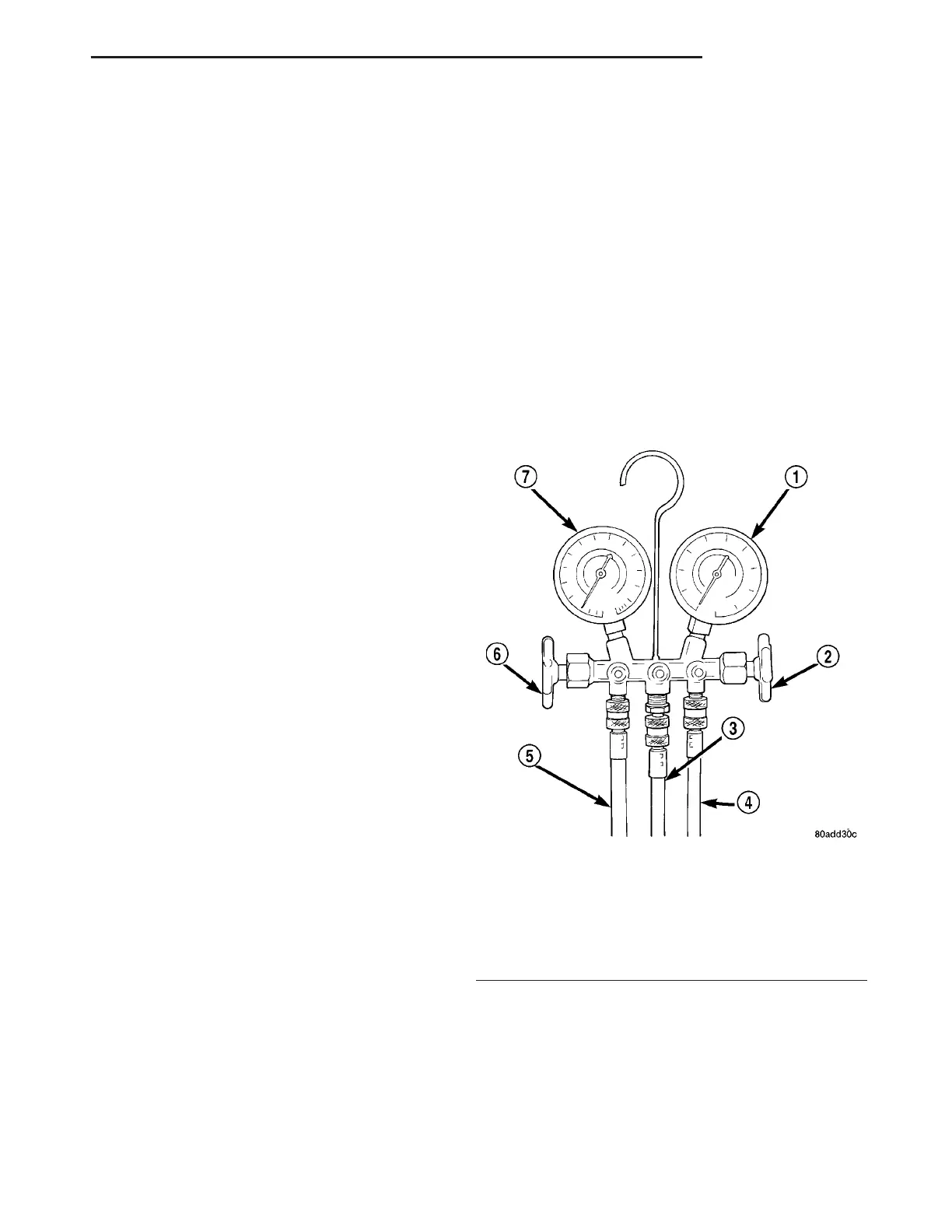
A manifold ga uge set may be needed wit h some
recovery/r ecycling/char ging equipment (Fig. 1). The
service hoses on the gauge set bein g used should
have man ual (tur n wh eel), or au tomat ic ba ck-flow
valves at the service port con nector en ds. This will
pr event r efrigera nt from being released in to the
atmosphere.
MANIFOLD GAUGE SET CONNECTIONS
CAUTION: Do not use an R-12 manifold gauge set
on an R-134a system. The refrigerants are not com-
patible and system damage will result.
Fig. 1 Manifold Gauge Set - Typical
1 - HIGH PRESSURE GAUGE
2 - VALVE
3 - VACUUM/REFRIGERANT HOSE (YELLOW W/ BLACK
STRIPE)
4 - HIGH PRESSURE HOSE (RED W/ BLACK STRIPE)
5 - LOW PRESSURE HOSE (BLUE W/ BLACK STRIPE)
6 - VALVE
7 - LOW PRESSURE GAUGE
VA PLUMBING 24 - 63