(12) EXAMP LE: Th e a m bien t t em per a t u r e is 21°
C (70° F). The evapora tor inlet tu be tem per ature is
12° C (54° F) and the eva por ator out let tu be tem per-
ature is 10° C (50° F ). Subt ract th e inlet tube tem-
perat ure fr om the outlet tube t empera tur e. The
differen ce is -2° C (-4° F). With a -2° C (-4° F) t em-
perat ure differential at 21° C (70° F) am bien t t em-
perat ure, t he system is fully ch arged.
(13) Add en ough refr igeran t to br ing the refriger-
ant syst em up to a fu ll ch arge.
(14) Remove th e jumper wire fr om the low pres-
su re cycling clu tch switch wire harn ess con nector
and plu g th e connector back int o the switch .
A/CCOMPRESSOR
DESCRIPTION
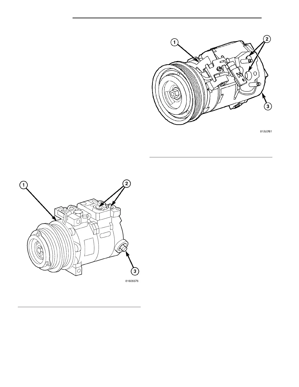
The stan da rd fron t A/C syst em uses a Denso
7SBU16C seven cylinder, var iable displacem ent
swash plate-t ype A/C compressor (Fig. 2). This A/C
compressor has a volume control which is regula ted
by an internal cont rol valve and has both the su ction
and dischar ge ports locat ed at th e rear of th e com-
pr essor.
The option al in dependant Konvekt a r ear A/C sys-
tem uses theDenso 10S17C ten cylin der, double-act -
ing swash plate-type A/C compressor (Fig. 3). This
A/C compressor has a fixed displacem ent of 170 cubic
centimet ers (10.374 cubic inches), a nd has both th e
su ction and discharge ports located on the cylinder
head a t the r ear of th e compressor.
A label ident ifying th e use of R-134a refr igerant is
locat ed on both A/C com pr essor s.
OPERATION
The A/C compressor is dr iven by the engine
through an electr ic clutch, drive pulley and belt
arrangement. The A/C compressor is lubr icat ed by
refriger ant oil tha t is cir culated th roughout the
refriger ant syst em with t he refrigerant.
The A/C compressor draws in low-pressure refrig-
eran t vapor from t he A/C evapora tor th rough its suc-
tion port . It th en compresses t he refr iger ant into a
high-pressure, high-t empera ture r efrigera nt va por,
which is t hen pu mped to th e A/C condenser through
the com pr essor discharge port.
The A/C compressor ca nnot be repaired and, if
faulty or dam aged, it must be r eplaced. Th e compres-
sor clutch, pulley and bearing assembly, and clu tch
field coil a re ava ila ble for service. If an interna l fail-
ure of the A/C com pr essor has occurr ed, the receiver /
dr ier mu st also be replaced.
DI AGN OSI S AN D T EST I N G
A / C COMPRESSOR NOISE
When investigating an air condit ioning related
noise, you mu st first know t he condit ions under
which the noise occu rs. These condition s inclu de:
weather, vehicle speed, t ransmission in gear or neu -
tral, engine speed, engine temperature, and any
other specia l condition s. Noises tha t develop during
air con ditionin g opera tion ca n often be mislea ding.
For exa mple: Wh at sounds like a failed front bea rin g
or conn ectin g rod, m ay be caused by loose bolts, nu ts,
Fig. 2 Denso 7SBU16C A/C Compressor
1 - A/C COMPRESSOR (DENSO 7SBU16C)
2 - SUCTION AND DISCHARGE PORT
3 - INTERNAL CONTROL VALVE
Fig. 3 Denso 10S17C A/C Compressor
1 - A/C COMPRESSOR (DENSO 10S17C)
2 - SUCTION AND DISCHARGE PORT
3 - CYLINDER HEAD
24 - 66 PLUMBING VA