INSTALLATION
NOTE: Be certain to add refrigerant oil if the rear
A/C evaporator is being replaced. The refrigerant oil
must be drained from the old evaporator and mea-
sured to determine the amount of refrigerant oil to
add to the new evaporator. Use only refrigerant oil
of the type recommended for the rear A/C compres-
sor in the vehicle.
(1) If the rear A/C evaporator is being replaced,
insta ll th e cor rect amount an d type of refrigerant oil
into th e new rear A/C evapora tor. Dr ain the old evap-
orator and measure th e refrigera nt oil. Fill the new
evapor ator wit h t he same a mount of new r efrigera nt
oil t hat wa s dr ained ou t of the old eva por ator.
(2) Position th e rea r A/C evaporator to the bottom
of the rear A/C evaporator housin g an d in st all four
new rivets.
(3) Position the thr ee cover s to th e rea r A/C evap-
orator and in st all eight new rivets.
(4) In st all th e left blower m otor ont o the rear A/C
evapor ator h ousing (Refer to 24 - H EATING & AIR
CONDITIONING/DISTRIBUTION - RE AR/BLOWER
MOTOR - INSTALLATION).
(5) Connect the rea r A/C expansion va lve to the
rear A/C eva por ator and insta ll n ew insulating tape
(Refer to 24 - HE ATING & AIR CONDITIONING/
PLUMBING/REAR A/C EXPANSION VALVE -
INSTALLATION).
(6) Position t he conden sa te dra in pa n to the bot-
tom of the rea r A/C evaporator and install t he five
scr ews and wa sh ers th at secu re th e drain pan to the
evapor ator. Tight en th e screws to 2.2 N·m (20 in.
lbs.).
(7) In st all th e rear A/C evapora tor h ousing (Refer
to 24 - HEATING & AIR CONDITIONING/DISTRI-
BUTION/REAR A/C EVAP ORATOR HOUSING -
INSTALLATION).
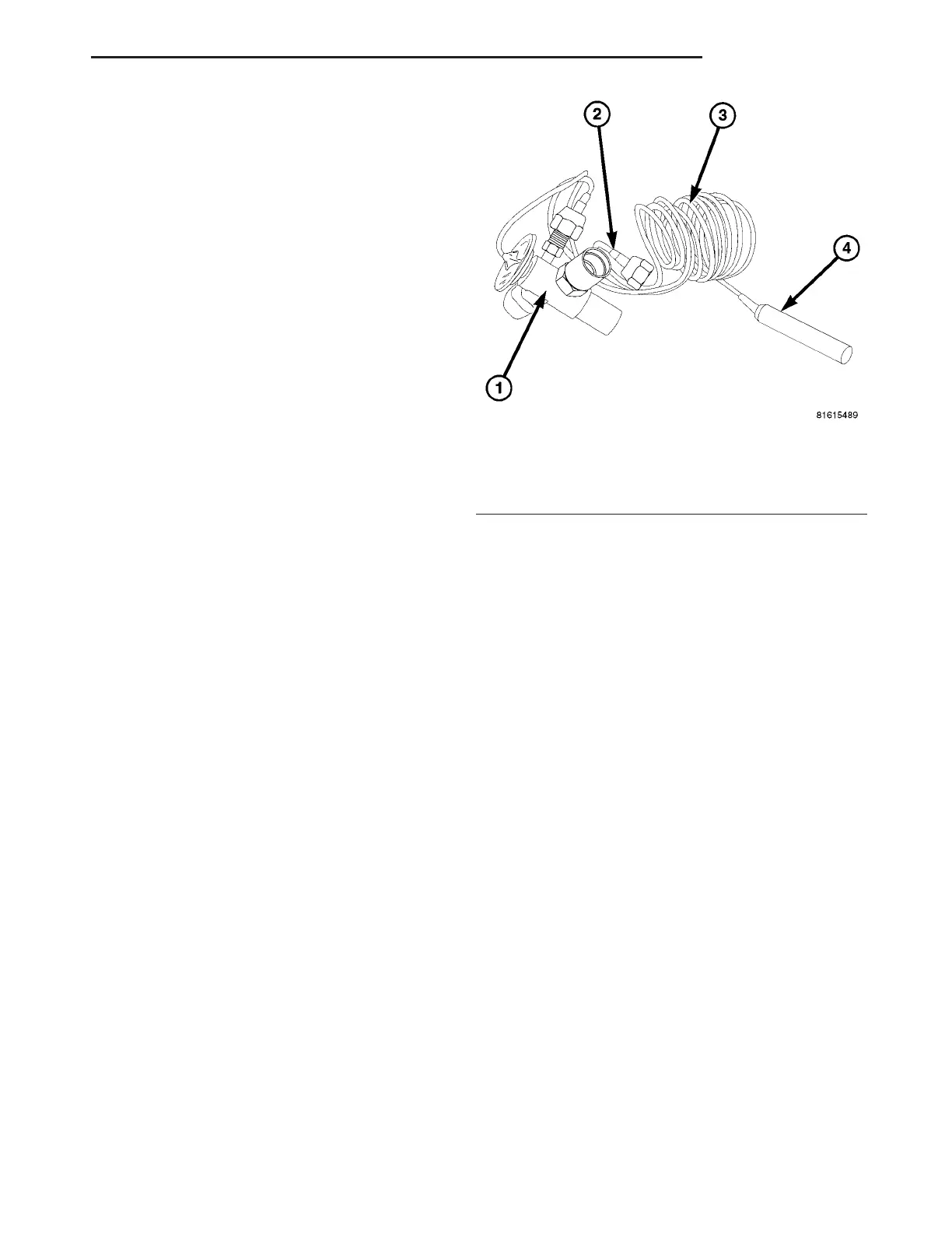
REAR A / C EX PAN SI ON VALV E
DESCRIPTION
The rear A/C expan sion valve con trols the am ount
of refr iger ant enter ing th e rear A/C evaporator (Fig.
24). The rea r A/C expansion valve is of an extern ally-
equalized t herm ostatic expansion valve (TXV) design
and consist s of a cast metal body with a rem ovable
equalizer tube an d an integra l thermal sensor wh ich
uses a capilla ry t ube and sensing bulb.
The rea r A/C expansion valve is locat ed t o the left
of the rear blower motors in the r ear evapora tor
housin g.
OPERATION
High-pressure, high tempera ture liquid r efrigera nt
from the liqu id line passes through the expansion
valve orifice, con vert ing it in to a low-pressur e, low-
temper ature mixt ure of liqu id an d gas before it
enters the A/C evaporator. A t herm al sensor in th e
rear A/C expansion valve monitor s t he tem perat ure
of the refriger ant leaving the r ear evaporator by use
of a sen sing bulb positioned next t o t he evapora tor
outlet tube. The therma l sensor a djusts t he orifice
size at th e eva por ator in let to allow th e proper
amount of refriger ant into th e rea r A/C eva por ator in
order to meet vehicle cooling requirem ents. Con trol-
lin g the refrigerant flow th rough th e A/C evaporator
ensures that none of the refriger ant leaving the evap-
orator is st ill in a liquid st ate, wh ich could ca use
da mage to the A/C com pr essor.
To overcome the effect of the pr essu re drop with in
the rea r A/C evapor ator, an ext erna l equ alizer tube is
connect ed to t he evapor ator outlet t ube and run s to
the u nderside if the dia ph ragm within th e expan sion
valve .
The rea r A/C expa nsion valve is factory calibra ted
and ca nnot be adjusted or repaired a nd, if faulty or
da maged, it must be replaced.
Fig. 24 Rear A/C Expansion Valve
1 - REAR A/C EXPANSION VALVE
2 - EQUALIZER TUBE
3 - CAPILLARY TUBE
4 - SENSING BULB
VA PLUMBING 24 - 85