INSTALLATION
(1) Remove the t ape or plugs from the r ear refr ig-
eran t line an d evapora tor tu be fittings a nd the rear
expan sion valve por ts.
(2) Lubricate a n ew O-ring sea l wit h clea n refr ig-
eran t oil and insta ll it onto the rear evapora tor inlet
tube fitt ing. Use only the specified O-r ing seal as it is
made of a specia l material for th e R-134a system.
Use only refriger ant oil of the type r ecommen ded for
the r ear A/C compressor in t he vehicle.
(3) In st all th e rea r A/C expansion va lve onto t he
rear evaporator inlet tube. Tighten t he nut to 35 N·m
(26 ft. lbs.).
(4) Lubricate a n ew O-ring sea l wit h clea n refr ig-
eran t oil a nd install it onto t he rear liquid line fit-
ting. Use only the specified O-ring seal as it is made
of a special m ater ial for th e R-134a system . Use on ly
refriger ant oil of the type recom mended for the r ear
A/C compressor in the vehicle.
(5) Connect the rea r liqu id lin e to the rear A/C
expan sion valve. Tighten the nut to 35 N·m (26 ft.
lbs.).
(6) Connect the equalizer tube to the r ear evapora-
tor out let tube. Tighten the nut to 10 N·m (88 in .
lbs.).
(7) Position t he rear expan sion valve sensin g bulb
onto the rea r evaporator outlet tube and install the
reta ining clam p secu rely.
(8) In st all n ew insulating t ape around the rea r A/C
expan sion valve area .
(9) Reconnect t he negat ive batt ery cable.
(10) Eva cuat e th e rear refriger ant system (Refer t o
24 - HEATING & AIR CONDITIONING/P LUMBING
- STANDARD PROCEDURE - REFRIGERANT SYS-
TEM EVACUATE).
(11) Char ge the rea r refr iger ant system (Refer to
24 - HEATING & AIR CONDITIONING/P LUMBING
- STANDARD PROCEDURE - REFRIGERANT SYS-
TEM CH ARGE).
(12) Install the cover onto the rea r A/C evaporator
housin g (Refer to 24 - H EATING & AIR CONDI-
TIONING/DISTRIBUTION - REAR/A/C EVAPORA-
TOR COVE R-REAR - INSTALLATION).
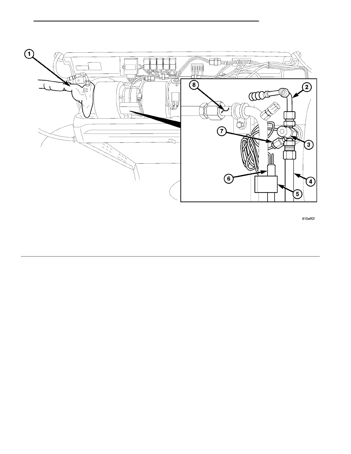
Fig. 25 Rear A/C Expansion Valve
1 - INSULATING TAPE
2 - REAR LIQUID LINE
3 - REAR A/C EXPANSION VALVE
4 - REAR A/C EVAPORATOR INLET TUBE
5 - RETAINING CLAMP
6 - SENSING BULB AND CAPILLARY TUBE
7 - EQUALIZER TUBE
8 - REAR A/C EVAPORATOR OUTLET TUBE
VA PLUMBING 24 - 87