INSTALLATION
CONDENSER TO RECEIVER / DRIER
(1) Remove the ta pe or plu gs from t he rear liquid
lin e fitt ings and r eceiver/drier and conden ser por ts.
(2) Lubricate new O-ring seals with clean refriger-
ant oil a nd insta ll them on to the rea r liquid line fit-
tings. Use on ly t he specified O-ring sea ls as th ey are
made of a specia l material for th e R-134a system.
Use only refriger ant oil of the type r ecommen ded for
the r ear A/C compressor in t he vehicle.
(3) Connect the rea r liquid line to the rear receiv-
er/drier. Tigh ten the nut to 35 N·m (26 ft. lbs.).
(4) Connect the rea r liqu id lin e to the rear A/C
condenser. Tighten t he nu t to 35 N·m (26 ft . lbs.).
(5) In st all t he retaining str aps that secur e t he rear
A/C wir e har ness to t he rear liquid lin e.
(6) Reconnect t he negat ive batt ery cable.
(7) Eva cuate th e rear refr iger ant system (Refer to
24 - HEATING & AIR CONDITIONING/P LUMBING
- STANDARD PROCEDURE - REFRIGERANT SYS-
TEM EVACUATE).
(8) Char ge the r ear refr igerant syst em (Refer to 24
- HEATING & AIR CONDITIONING/P LUMBING -
STANDARD PROCEDURE - REFRIGE RANT SYS-
TEM CH ARGE).
(9) In st all th e rea r air filter (Refer to 24 - HEAT-
ING & AIR CONDITIONING/DISTRIBUTION -
REAR/AIR FILTE R - INSTALLATION).
(10) Install t he cover onto the rear A/C condenser
housin g (Refer to 24 - H EATING & AIR CONDI-
TIONING/DISTRIBUTION - REAR/A/C CON-
DENSER COVE R - INSTALLATION).
RESERVOIR TO EXPANSION VALVE
(1) Remove the ta pe or plu gs from t he rear liquid
lin e fittings and t he reservoir a nd expansion valve
por ts.
(2) Lubricate new O-ring seals with clean refriger-
ant oil a nd insta ll them on to the rea r liquid line fit-
tings. Use on ly t he specified O-ring sea ls as th ey are
made of a specia l material for th e R-134a system.
Use only refriger ant oil of the type r ecommen ded for
the r ear A/C compressor in t he vehicle.
(3) Connect the rea r liqu id lin e to the rear A/C
expan sion valve. Tighten the nut to 35 N·m (26 ft.
lbs.).
(4) Route the liqu id line thr ough t he opening in
the r oof and en gage th e grom met to t he roof pa nel.
(5) Connect t he rear liquid lin e to th e rea r r efrig-
eran t reser voir. Tigh ten t he nu t to 35 N·m (26 ft.
lbs.).
(6) Reconnect t he negat ive batt ery cable.
(7) Eva cuate th e rear refr iger ant system (Refer to
24 - HEATING & AIR CONDITIONING/P LUMBING
- STANDARD PROCEDURE - REFRIGERANT SYS-
TEM EVACUATE).
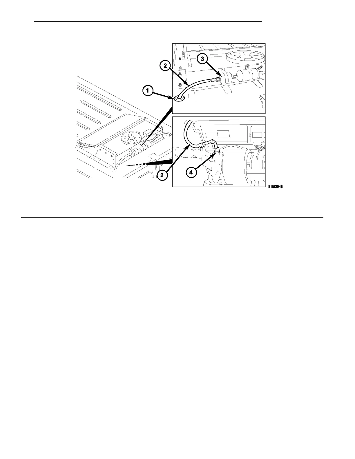
Fig. 32 Rear Liquid Line - Reservoir to Expansion Valve
1 - GROMMET
2 - LIQUID LINE (TO EXPANSION VALVE)
3 - REAR REFRIGERANT RESERVOIR
4 - REAR A/C EXPANSION VALVE
VA PLUMBING 24 - 93