(2) In st all a new rear receiver/drier (Refer to 24 -
HEATING & AIR CONDITIONING/PLUMBING/
REAR RE CEIVER/DRIE R - INSTALLATION).
(3) Position the rear r efrigera nt reser voir to the
rear A/C condenser housing an d in stall th e ret ain ing
bracket and bolt. Tight en t he bolt to 25 N·m (18 ft.
lbs.).
(4) Remove the ta pe or plu gs from t he rear liquid
lin e fitt ing and receiver/drier and r eservoir ports.
(5) Lubricate a n ew O-ring sea l wit h clea n refr ig-
eran t oil and install it ont o th e rear receiver /dr ier fit-
ting. Use only the specified O-ring seal as it is made
of a special m ater ial for th e R-134a system . Use on ly
refriger ant oil of the type recom mended for the r ear
A/C compressor in the vehicle.
(6) Connect th e rear receiver/dr ier to the rea r
refriger ant r eservoir. Tight en the nu t to 35 N·m (26
ft. lbs.).
(7) Lubricate a n ew O-ring sea l wit h clea n refr ig-
eran t oil a nd install it onto t he rear liquid line fit-
ting. Use only the specified O-ring seal as it is made
of a special m ater ial for th e R-134a system . Use on ly
refriger ant oil of the type recom mended for the r ear
A/C compressor in the vehicle.
(8) Connect t he rear liquid lin e to th e rea r r efrig-
eran t reser voir. Tigh ten t he nu t to 35 N·m (26 ft.
lbs.).
(9) Reconnect t he negat ive batt ery cable.
(10) Eva cuat e th e rear refriger ant system (Refer t o
24 - HEATING & AIR CONDITIONING/P LUMBING
- STANDARD PROCEDURE - REFRIGERANT SYS-
TEM EVACUATE).
(11) Char ge the rea r refr iger ant system (Refer to
24 - HEATING & AIR CONDITIONING/P LUMBING
- STANDARD PROCEDURE - REFRIGERANT SYS-
TEM CH ARGE).
(12) Install th e rear air filter (Refer t o 24 - HEAT-
ING & AIR CONDITIONING/DISTRIBUTION -
REAR/AIR FILTE R - INSTALLATION).
(13) Install t he cover onto the rear A/C condenser
housin g (Refer to 24 - H EATING & AIR CONDI-
TIONING/DISTRIBUTION - REAR/A/C CON-
DENSER COVE R - INSTALLATION).
REAR SU CT I ON LI N E
DESCRIPTION
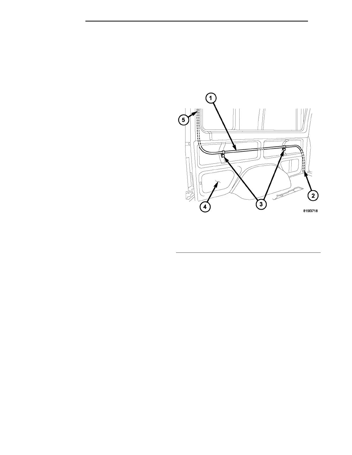
The rear A/Csuction line is th e refr igerant lin e that
carries refr igerant from the rear A/C evapora tor to
the A/C underbody suction lin e (Fig. 35). The r ear
A/C suction line is retained t o the left qu arter pa nel
by two plastic retainin g clips.
CAUTION: Use only seals specified for the vehicle.
Failure to use the correct seals will cause the refrig-
erant system connections to leak.
The rea r A/C suction line has no servicea ble parts
except for the O-ring seals. The O-rin g sea ls used on
the conn ection s are ma de from a special t ype of ru b-
ber not affected by R-134a refrigerant and must be
repla ced when ever t he rear A/C suction line is
removed an d insta lled.
If the rear A/C suct ion line is found to be leakin g
or da maged, it mu st be replaced.
REMOVAL
WARNING: Refer to the applicable warnings and
cautions for this system before performing the fol-
lowing operation (Refer to 24 - HEATING & AIR
CONDITIONING/PLUMBING - WARNINGS) and (Refer
to 24 - HEATING & AIR CONDITIONING/PLUMBING -
CAUTIONS). Failure to follow the warnings and cau-
tions could result in possible personal injury or
death.
(1) Disconn ect and isolate the negat ive ba tter y
cable.
(2) Remove th e cover from the rea r A/C evapor ator
housin g (Refer to 24 - H EATING & AIR CONDI-
TIONING/DISTRIBUTION - REAR/A/C EVAPORA-
TOR COVE R-REAR - RE MOVAL).
(3) Recover the refr iger ant from the rear r efriger-
ant system (Refer to 24 - HEATING & AIR CONDI-
TIONING/PLUMBING - STANDARD PROCEDURE -
REFRIGERANT RECOVERY).
(4) Remove the in su lat ing tape from around the
area of the rea r A/C suct ion l ine and evapor ator out-
let tu be (Fig. 36).
Fig. 35 Rear A/C Suction Line
1 - REAR A/C SUCTION LINE
2 - TO UNDERBODY SUCTION LINE
3 - RETAINING CLIPS
4 - LEFT INNER QUARTER PANEL
5 - TO REAR A/C EVAPORATOR
24 - 96 PLUMBING VA