INSTALLATION
(1) Remove the tape or plugs fr om the rear su ction
and underbody line fittings and the rea r evaporator
tube.
(2) Lubricate new O-ring seals with clean refriger-
ant oil and in st all them on to the rear suction line fit -
tings. Use on ly t he specified O-ring sea ls as th ey are
made of a specia l material for th e R-134a system.
Use only refriger ant oil of the type r ecommen ded for
the r ear A/C compressor in t he vehicle.
(3) Position the rear A/C suction line t o the left
inne r q uarte r p ane l and ins tall it into the tw o re tain-
ing clips.
(4) From inside th e vehicle, con nect th e rear A/C
su ction line to th e rea r A/C eva por ator. Tighten the
nut to 35 N·m (26 ft. lbs.).
(5) From undern eath the vehicle, connect th e rea r
A/C suction lin e to the under body su ction line.
Tighten t he nu t to 35 N·m (26 ft . lbs.).
(6) In st all the thr ee foam insulators to the left
inne r q uarte r p ane l.
(7) In st all th e foam ru bber seal in to the floor
panel.
(8) In st all th e left quarter tr im pa nel (Refer t o 23 -
BODY/INTERIOR/QUARTER TRIM PANEL -
INSTALLATION).
(9) Reconnect t he negat ive batt ery cable.
(10) Eva cuat e th e rear refriger ant system (Refer t o
24 - HEATING & AIR CONDITIONING/P LUMBING
- STANDARD PROCEDURE - REFRIGERANT SYS-
TEM EVACUATE).
(11) Char ge the rea r refr iger ant system (Refer to
24 - HEATING & AIR CONDITIONING/P LUMBING
- STANDARD PROCEDURE - REFRIGERANT SYS-
TEM CH ARGE).
(12) Install the cover onto the rea r A/C evaporator
housin g (Refer to 24 - H EATING & AIR CONDI-
TIONING/DISTRIBUTION - REAR/A/C EVAPORA-
TOR COVE R-REAR - INSTALLATION).
REFRI GERAN T LI N E COU PLER
DESCRIPTION
A spr ing-lock type refriger ant line coupler is used
to connect the front sect ion of th e un der body dis-
charge line to the compressor section of the discha rge
lin e. A secondar y reta ining clip may be installed over
the con nected coupler for added prot ection .
The spring-lock r efrigera nt line coupler requires a
special disconn ect tool for disen gaging th e two cou-
pler halves.
OPERATION
The spr ing-lock coupler is held togeth er by a garter
spring inside a circular cage on t he male half of th e
fitting (Fig. 37). When t he two coupler halves a re
connect ed, the fla red end of the fema le fitt ing slips
behind th e garter spring inside th e cage on t he male
fitting. The gart er sprin g an d ca ge prevent the flared
end of the fem ale fitting from pulling out of the
cage.
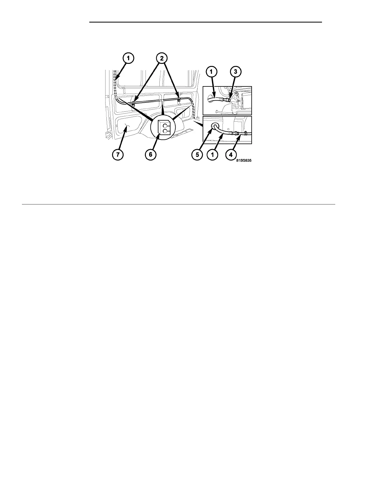
Fig. 36 Rear A/C Suction Line
1 - REAR A/C SUCTION LINE
2 - RETAINING CLIPS
3 - EVAPORATOR OUTLET TUBE
4 - UNDERBODY SUCTION LINE
5 - FOAM RUBBER SEAL
6 - FOAM INSULATORS
7 - LEFT INNER QUARTER PANEL
24 - 98 PLUMBING VA