Two O-rings on t he ma le half of th e fitting ar e
used t o seal th e connection. Th ese O-r ings a re com-
pa tible with R-134a refr iger ant a nd must be r eplaced
with O-rin gs made of the same mat eria l.
Secondary clips ar e installed over the two con-
nected coupler halves at th e factory for a dded blowoff
pr otection. In addition, some m odels h ave a plast ic
ring that is used at the factor y a s a visua l indica tor
to confirm tha t these couplers are connected. After
the cou pler is connect ed, the plastic indicator ring is
no longer needed; h owever, it will r emain on the
refriger ant line near t he coupler cage.
REMOVAL
WARNING: Refer to the applicable warnings and
cautions for this system before performing the fol-
lowing operation (Refer to 24 - HEATING & AIR
CONDITIONING/PLUMBING - WARNINGS) and (Refer
to 24 - HEATING & AIR CONDITIONING/PLUMBING -
CAUTIONS). Failure to follow the warnings and cau-
tions could result in possible personal injury or
death.
(1) Recover th e refriger ant from th e refriger ant
system (Refer t o 24 - HEATING & AIR CONDITION-
ING/PLUMBING - STANDARD PROCE DURE -
REFRIGERANT SYSTEM RECOVE RY).
(2) Remove the secon da ry retaining clip from t he
spring-lock coupler.
(3) Fit t he proper size A/C line disconnect tool
(Special Tool Kit 7193) over th e spring-lock cou pler
cage (Fig. 38).
(4) Close t he t wo halves of the A/C lin e disconn ect
tool a round the sprin g-lock coupler.
(5) Push t he A/C line disconnect tool int o t he open
side of t he coupler cage to expan d the gar ter sprin g.
Once th e gar ter sprin g is expanded and while still
pu sh ing the disconnect t ool in to th e open side of t he
coupler ca ge, pull on t he refr iger ant line att ached t o
the fema le h alf of the coupler fitting un til th e fla nge
on t he female fitting is separ ated from the gart er
spring and cage on th e male fitting with in the dis-
connect t ool.
NOTE: The garter spring may not release if the A/C
line disconnect tool is cocked while pushing it into
the coupler cage opening.
(6) Open an d remove th e A/C line disconnect tool
from the disconnect ed spr ing-lock coupler.
(7) Complet e th e separa tion of the two halves of
the cou pler fit ting.
INSTALLATION
(1) Check to ensure that t he garter spring is
locat ed within th e ca ge of the ma le coupler fitting,
and that the gar ter sprin g is n ot da maged.
(a) If the gar ter sprin g is missing, in st all a new
spring by pushing it in to the cou pler cage openin g.
(b) If th e gart er spring is damaged, remove it
from th e coupler cage with a small wir e hook (DO
NOT use a screwdr iver) a nd insta ll a new gart er
sprin g.
(2) Clean an y dirt or foreign material from both
halves of t he coupler fitting.
(3) In st all new O-r ings on t he male half of the cou-
pler fit ting.
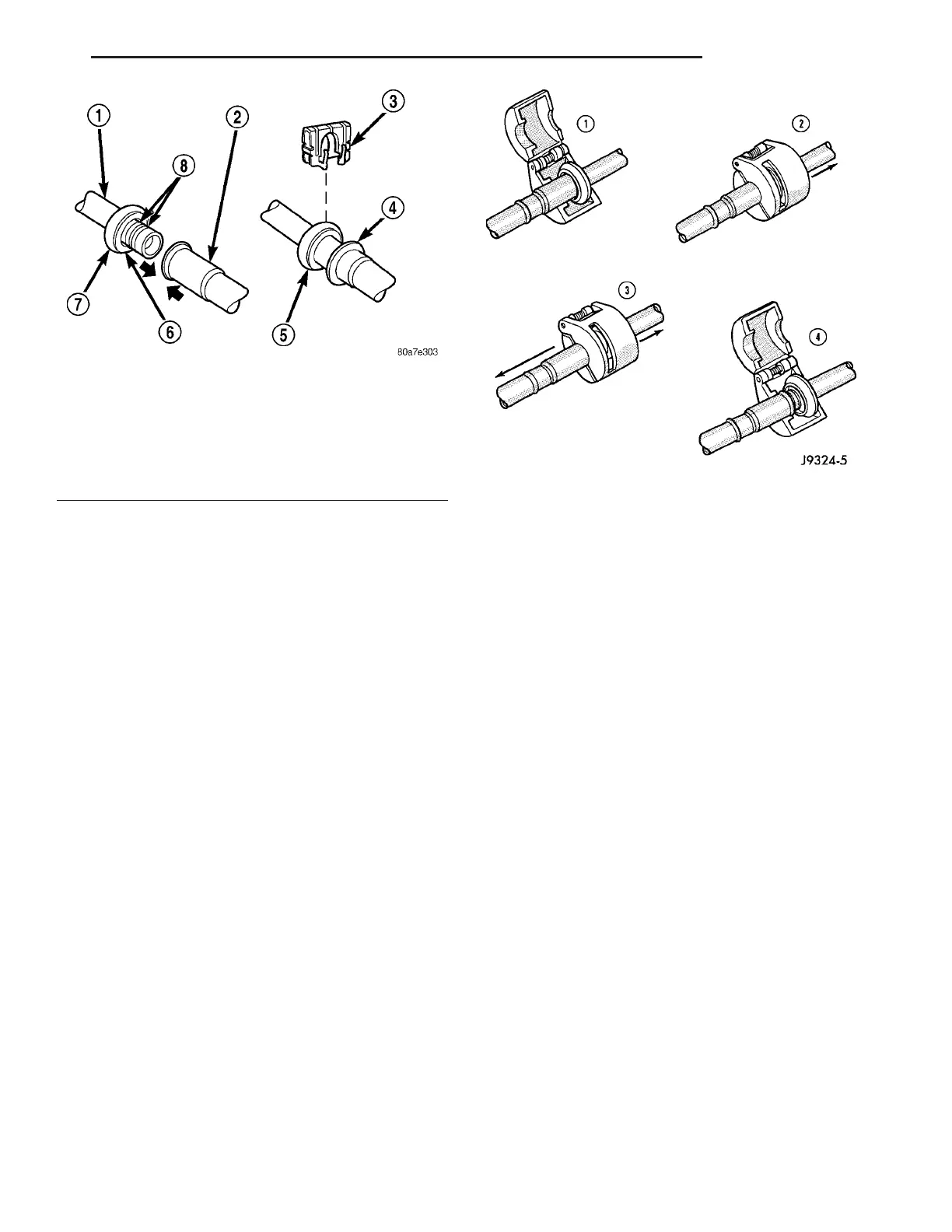
Fig. 37 Spring-Lock Coupler - Typical
1 - MALE HALF SPRING-LOCK COUPLER
2 - FEMALE HALF SPRING-LOCK COUPLER
3 - SECONDARY CLIP
4 - CONNECTION INDICATOR RING
5 - COUPLER CAGE
6 - GARTER SPRING
7 - COUPLER CAGE
8 - O-RING SEALS
Fig. 38 Refrigerant Line Spring-Lock Coupler
Disconnect
VA PLUMBING 24 - 99