SUCTION LINE - REAR SECTION
(1) Remove th e cover from the rea r A/C evapor ator
housin g (Refer to 24 - H EATING & AIR CONDI-
TIONING/DISTRIBUTION - REAR/A/C EVAPORA-
TOR COVE R-REAR - RE MOVAL).
(2) Recover the refr iger ant from the rear r efriger-
ant system (Refer to 24 - HEATING & AIR CONDI-
TIONING/PLUMBING - STANDARD PROCEDURE -
REFRIGERANT RECOVERY).
(3) Raise and support the vehicle.
(4) Remove the bolt that secures the connect ion of
the fr ont section of the un derbody su ction lin e to th e
rear sect ion of th e under body suct ion line (Fig. 41).
(5) Disconn ect the fr ont sect ion of t he u nderbody
su ction line from the rear sect ion a nd r emove and
discard t he O-ring seal.
(6) Disconn ect the rea r section of the underbody
su ction line from the rear A/C suction line an d
remove an d discard t he O-ring seal.
(7) In st all plu g in, or tape over all of the opened
su ction line fitt ings.
(8) Remove the screws a nd brackets th at secure
the rea r section of the under body su ction line to the
underneath of the vehicle and r emove th e rea r sec-
tion of t he suct ion line.
INSTALLATION
DISCHARGE LINE
(1) If th e compressor section of the un derbody dis-
charge lin e wa s rem oved fr om the A/C compressor,
remove plu gs or ta pe from the discha rge line fitting,
lubr icat e a new ru bber O-rin g seal with clean refr ig-
eran t oil, insta ll it onto t he disch arge line fitting and
insta ll the bolt that secu res th e discha rge lin e to the
compressor. Tighten t he bolt to 21 N·m (15 ft. lbs.).
(2) Position t he u nderbody disch arge line to the
vehicle.
(3) In st all the br ackets and screws t hat secu re the
underbody discha rge line to the under neat h of the
vehicle. Tighten t he screws to 8 N·m (70 in. lbs.).
(4) Engage the fuel lines to the retaining clips
locat ed near t he tr ansmission.
(5) In st all th e rear transmission crossmember
(Refer to 13 - F RAME & BUMPERS/FRAME/REAR
CROSSMEMBE R-TRANSMISSION - INSTALLA-
TION).
(6) Remove the plugs or tape from the disch arge
lin e fitt ings.
(7) Lubricate new rubber O-r ing seals wit h clea n
refriger ant oil an d insta ll t hem onto the dischar ge
lin e fitt ings.
(8) Connect th e underbody disch arge lin e spring-
lock coupler to the compressor sect ion of the dis-
charge line and insta ll the secondary ret ain ing clip
(if equipped) (Refer t o 24 - HEATING & AIR CONDI-
TIONING/PLUMBING/REFRIGERANT LINE COU-
PLER - INSTALLATION).
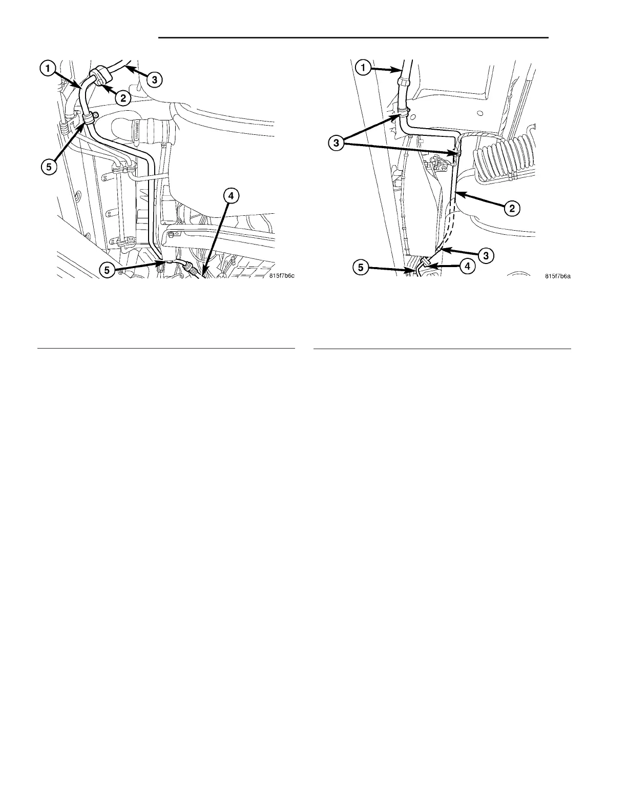
Fig. 40 Underbody Suction Line - Front Section
1 - UNDERBODY SUCTION LINE-FRONT SECTION
2 - BOLT
3 - UNDERBODY SUCTION LINE-REAR SECTION
4 - SUCTION LINE-COMPRESSOR SECTION
5 - SCREW AND BRACKET (2)
Fig. 41 Underbody Suction Line - Rear Section
1 - REAR A/C DISCHARGE LINE
2 - UNDERBODY SUCTION LINE-REAR SECTION
3 - SCREW AND BRACKET (3)
4 - BOLT
5 - UNDERBODY SUCTION LINE-FRONT SECTION
24 - 102 PLUMBING VA