(3) Remove the cla mp a t th e flexible pipe conn ec-
tion an d t he supplem enta l hea ter hou sing (if
required).
(4) Remove th e th ree screws holding the exh aust
pipe to the body.
(5) Remove the steel exhau st pipe from the vehi-
cle.
(6) Remove th e flexible exhaust pipe from the
vehicle (if required).
INSTALLATION
(1) In st all t he flexible exhaust pipe to the heater
unit. Tight en moun ting clamp securely.
(2) Position t he steel exha ust pipe to the flexible
exha ust and in st all a nd tight en th e mounting clamp
securely.
(3) In st all th e three exhau st pipe screws, adjust
pipe placem ent as needed a nd tight en th e screws
securely.
(4) In st all the clam p to con nect th e steel exhau st
pipe to th e flexible exhaust pipe and tighten clam p
securely.
(5) Check exhau st pipe exha ust end pla cement and
make any final adjustm ents.
(6) Lower th e vehicle.
FU EL DOSI N G PU M P
DESCRIPTION
The dosing pu mp is a combined delivery, dosing
and shu t-off system for th e fuel supply to the su pple-
ment al ca bin hea ter from t he vehicle fuel ta nk.
OPERATION
The dosin g pump is an elect rically operated pump
that receives its oper ation instr uction s from the sup-
plemen tal cabin heat er control module. The pu mp
su pplies diesel fuel from th e vehicle fuel ta nk to th e
cabin h eater.
REMOVAL
NOTE: The dosing pump is serviceable without
removing the component from the vehicle.
(1) Disconn ect the rubber hose a t the fuel lin e to
heat er fuel pum p. Leave the r ubber hose on th e fu el
lin e (Refer to 24 - HE ATING & AIR CONDITION-
ING/CABIN HEATE R/FUEL LINE - REMOVAL)
(Fig. 2).
(2) Disconn ect the fuel lin e between th e dosin g
pu mp and the cabin hea ter unit.
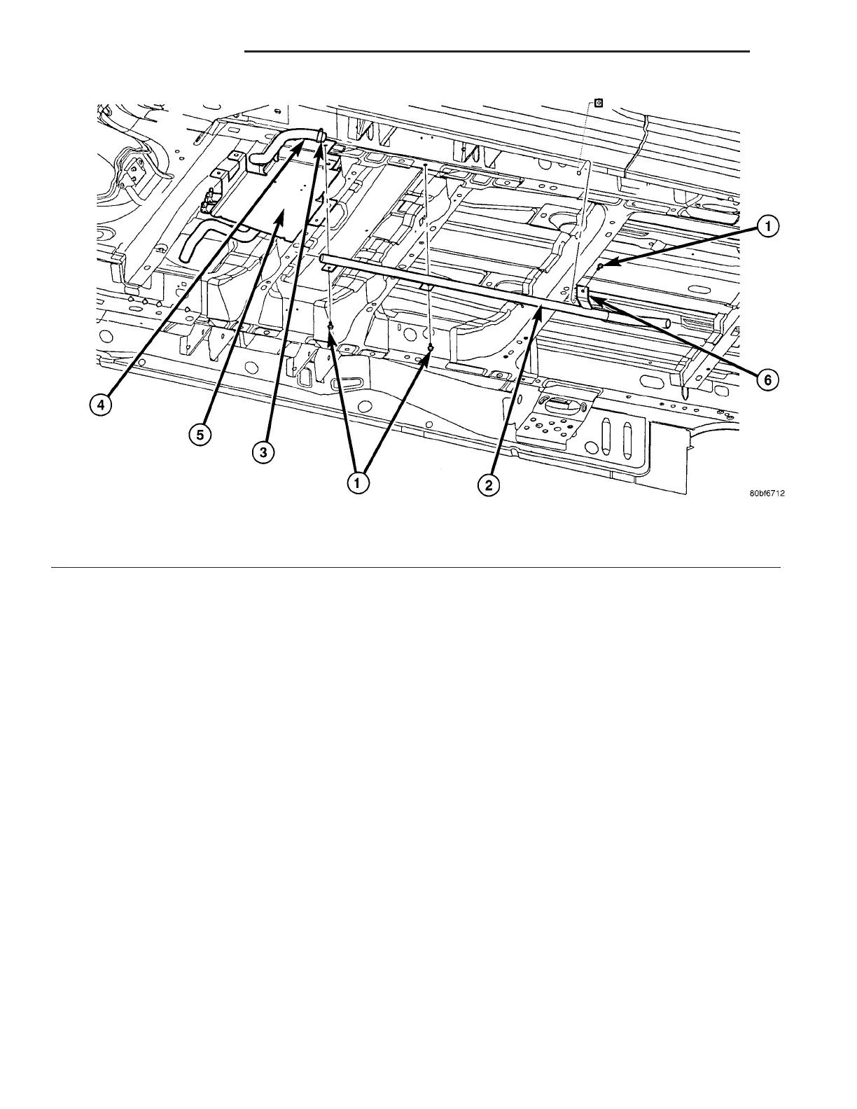
Fig. 1 Cabin Heater Exhaust System
1 - MOUNTING SCREW (3)
2 - STEEL HEATER EXHAUST PIPE
3 - EXHAUST CLAMP (2)
4 - FLEXIBLE HEATER EXHAUST PIPE
5 - HEATER SHIELD
6 - EXHAUST PIPE MOUNTING CLIP (3)
24 - 106 CABIN HEATER VA