HOIST
A vehicle ca n be lifted with:
• A sin gle-post, frame-con tact hoist.
• A twin-post, chassis hoist.
• A ra mp-type, drive-on hoist.
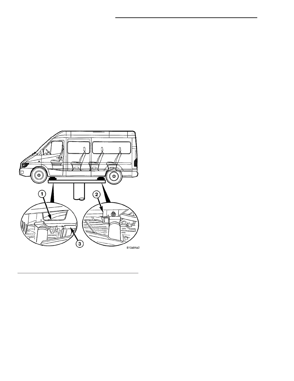
NOTE: When a frame-contact type hoist is used,
verify that the lifting pads are positioned properly.
The forward lifting pads should be positioned
against the forward flange of the transmission
crossmember brackets at the bottom of the frame
rail. The real lifting pads should be wedged
between the forward flange of the leaf spring
bracket and the frame rail. Safety stands should be
placed under the frame rails at the front and rear
ends.
JUMP STARTING
STANDARD PROCEDURE - JUMP STARTING
WARNING: REVIEW ALL SAFETY PRECAUTIONS
AND WARNINGS IN THE BATTERY SYSTEM SEC-
TION OF THE SERVICE MANUAL. (Refer to 8 -
ELECTRICAL/BATTERY SYSTEM/BATTERY - STAN-
DARD PROCEDURE)
• DO NOT JUMP START A FROZEN BATTERY,
PERSONAL INJURY CAN RESULT.
• IF EQUIPPED, DO NOT JUMP START WHEN
MAINTENANCE FREE BATTERY INDICATOR DOT IS
YELLOW OR BRIGHT COLOR.
• DO NOT JUMP START A VEHICLE WHEN THE
BATTERY FLUID IS BELOW THE TOP OF LEAD
PLATES.
• DO NOT ALLOW JUMPER CABLE CLAMPS TO
TOUCH EACH OTHER WHEN CONNECTED TO A
BOOSTER SOURCE.
• DO NOT USE OPEN FLAME NEAR BATTERY.
• REMOVE METALLIC JEWELRY WORN ON
HANDS OR WRISTS TO AVOID INJURY BY ACCI-
DENTAL ARCING OF BATTERY CURRENT.
• WHEN USING A HIGH OUTPUT BOOSTING
DEVICE, DO NOT ALLOW BATTERY VOLTAGE TO
EXCEED 16 VOLTS. REFER TO INSTRUCTIONS
PROVIDED WITH DEVICE BEING USED.
FAILURE TO FOLLOW THESE INSTRUCTIONS MAY
RESULT IN PERSONAL INJURY.
CAUTION: When using another vehicle as a
booster, do not allow vehicles to touch. Electrical
systems can be damaged on either vehicle.
TO JUMP START A DISABLED VEHICLE:
(1) Raise hood on disabled vehicle and visually
inspect en gine compartment for :
• Ba tter y cable clamp condition, clean if n ecessary.
• Frozen batt ery.
• Yellow or bright color test indicator, if equipped.
• Low battery fluid level.
• Generator drive belt condition and tension.
• Fuel fumes or leakage, correct if n ecessary.
CAUTION: If the cause of starting problem on dis-
abled vehicle is severe, damage to booster vehicle
charging system can result.
(2) When usin g another vehicle as a booster
sou rce, park the booster vehicle wit hin cable rea ch.
Turn off a ll accessories, set the par kin g brake, place
the automa tic tra nsmission in PARK or the manu al
transmission in NE UTRAL a nd turn the ignition
OFF.
(3) On disabled vehicle, place gea r selector in par k
or neut ral and set pa rk br ake. Turn off all accesso-
ries.
(4) Connect jumper cables to boost er battery. RED
clam p t o positive ter min al (+). BLACK cla mp to neg-
ative t erminal (-). DO NOT allow cla mps at opposite
end of cables to touch, electr ical arc will result.
Review all warn ings in this pr ocedure.
(5) On disabled vehicle, con nect RED jumper ca ble
clam p to positive (+) ter min al. Connect BLACK
jumper cable clam p to engine groun d as close t o the
ground cable attaching point a s possible.
Fig. 2 HOIST LOCATIONS
1 - TRANSMISSION CROSSMEMBER SUPPORT
2 - REAR LEAF SPRING MOUNT - FRONT
3 - TRANSMISSION CROSSMEMBER
0 - 6 LUBRICATION & MAINTENANCE VA