(3) In st all the stabilizer ba r clam p a nd bolts (Fig.
11). Tighten t he bolts to 30 N·m (22 ft. lbs.).
(4) Lower th e vehicle.
STABI LI Z ER LI N K
REMOVAL
(1) Raise and support the vehicle.
(2) In sert a pr y bar between th e stabilizer lin k a nd
som ething solid to pr y on.
(3) Pry the stabilizer link off th e stabilizer bar an d
the spring st op plate.
INSTALLATION
(1) In st all a mild detergent soap th e to rubber
bushings on t he stabilizer link.
(2) In st all the sta bilizer lin ks onto the stabilizer
bar an d spring st op plate by push ing on the lin k.
(3) Lower th e vehicle.
ST RU T
REMOVAL
(1) On the driver s side remove the floor covering
off to t he side.
(2) On the passen gers side t ake off the cover for
the t ools.
(3) Remove t he cover for the upper stru t mou nting
(Fig. 12).
(4) Remove the nut on t he upper strut mou nting
(Fig. 12).
(5) Raise and support the vehicle.
(6) Remove the front wh eels.
(7) Raise the lower control arm approxima tely 10
mm with a jack to rem ove the t ension from the st rut.
(8) Remove the st rut from th e steerin g kn uckle
(Fig. 12).
INSTALLATION
NOTE: Hand tighten the strut upper mounting nut
until the vehicle is on the ground, otherwise the
bushings may become distorted.
(1) In st all strut to the steerin g knu ckle (Fig. 12).
Tighten t o 185 N·m (136 ft . lbs.).
(2) Raise the lower cont rol to install the upper
pa rt of th e str ut into th e footwell. Tighten to 100
N·m (74 ft. lbs.).
(3) In st all wheels (Refer t o 22 - TIRES/WHEE LS/
WHEELS - INSTALLATION).
(4) Lower th e vehicle.
(5) In st all the nut covers (Fig. 12).
(6) Refit th e floor covering a nd the tool cover.
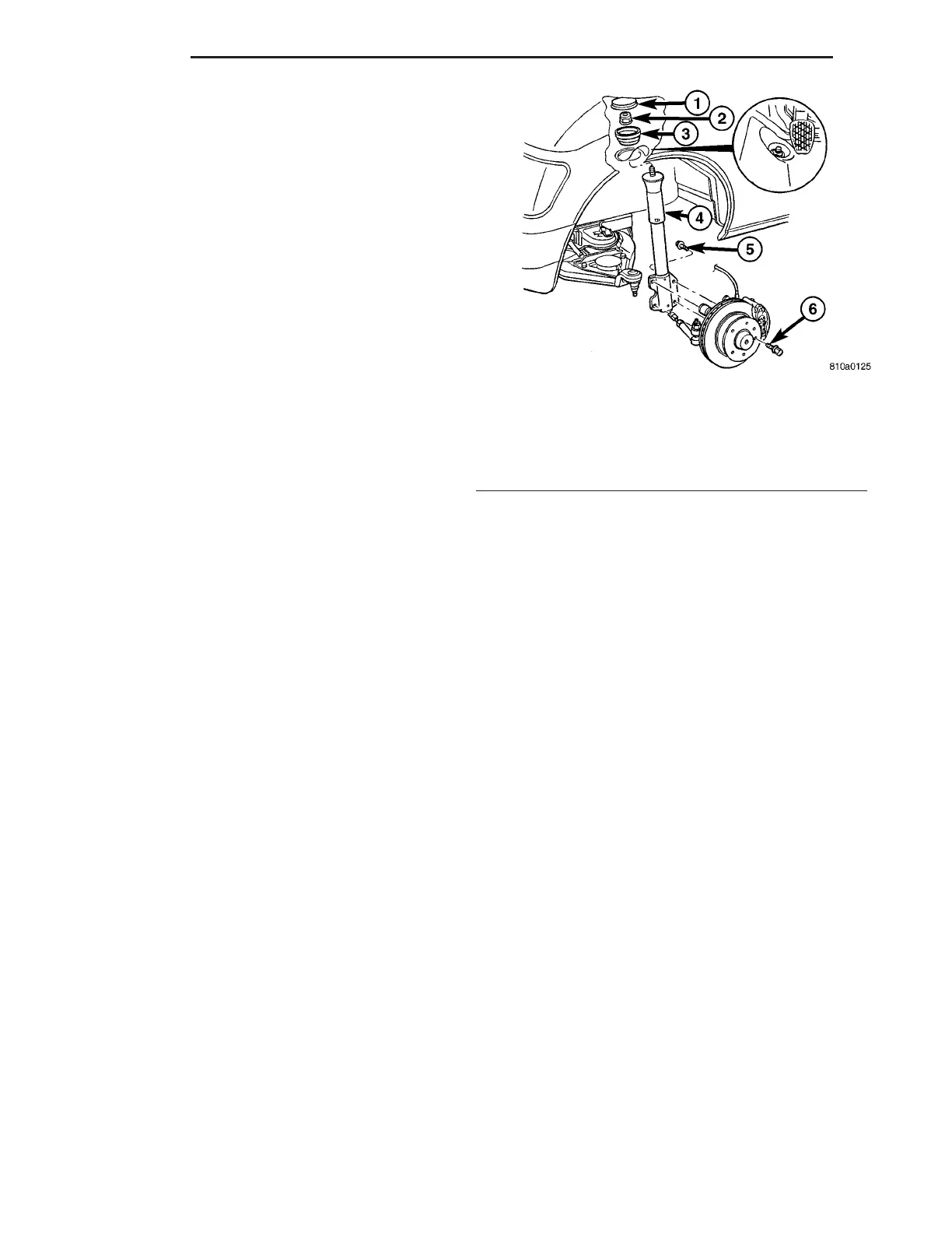
Fig. 12 STRUT
1 - COVER
2 - NUT
3 - RUBBER MOUNT
4 - STRUT
5 - STRUT BOLT
6 - LOCKING BOLT
2-10 FRONT VA