(5) Remove the spr ing clamp pla te and rubber
block.
(6) Remove t he shear bushings from the fron t and
rear bolts.
INSTALLATION
(1) In st all a jack under the lower ball joint an d
lower the weigh t of t he v ehicle enough t o allow a
wrench between t he lower cont rol arm and the
bracket tigh ten the nut.
(2) Fit one spring clamp pla te together with the
lower spring rubber block.
(3) In st all the bolt with the sh ear bu shing on t he
rear m ounting, Do not tighten yet.
(4) In st all the fou r retaining bolts for the spring
clam p plate. Tighten to 65 N·m (48 ft.lbs.).
(5) Align the holes for th e front clamp pla te joint
using a suitable drift (shear bu sh ing not in st alled).
(6) Remove the alignment drift.
(7) In sert the shear bu shing an d retaining bolt
into the hole and tight en to 130 N·m (96 ft.lbs.).
(8) Remove the jack an d lower the veh icle.
SPRI N G ST OP PLAT ES
REMOVAL
(1) Raise and support the vehicle.
(2) Remove the tir e and wh eel a ssem bly.
(3) Remove the lower en d of the sta bilizer link
from the stop plate.
(4) Remove the three bolts r etaining th e spring
st op plate from th e lower con trol arm .
INSTALLATION
(1) In st all the spr ing stop plate to th e lower con-
trol arm . Tighten the bolts t o 60 N·m (44 ft. lbs.).
(2) In st all the stabilizer link to the spring stop
plat e.
(3) In st all the tir e and wh eel a ssem bly.
(4) Lower th e vehicle.
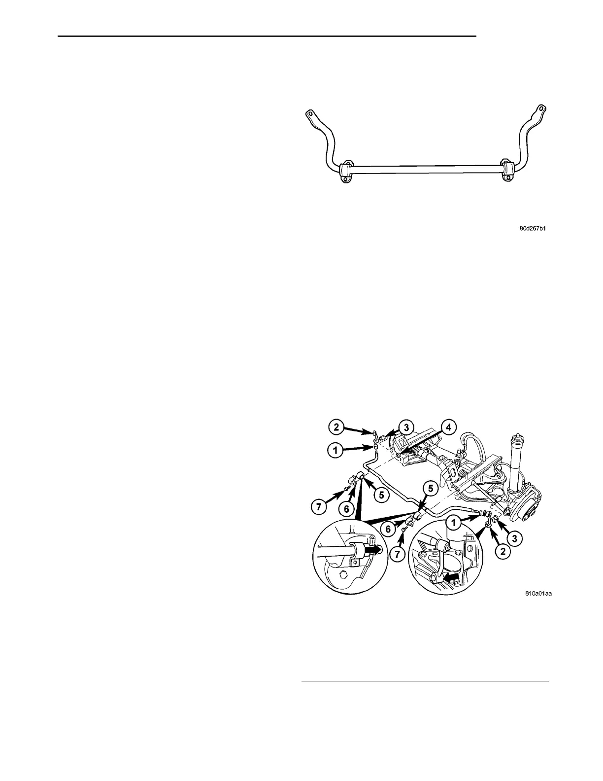
STABI LI Z ER BAR
DESCRIPTION
The bar extends across the fron t un derside of the
chassis and conn ects to the fra me crossmem ber. The
ends of t he ba r mount to th e lower suspension a rm.
All mountin g points of the stabilizer bar are isolated
by bu sh ings (Fig. 10).
OPERATION
The st abilizer ba r is used to min imize vehicle fr ont
sway dur ing t urns. The ba r helps t o m ain tain a flat
attitude to th e road sur face.
REMOVAL
(1) Raise and support the vehicle.
(2) Remove the sta bilizer ba r clamp bolt s at th e
front axle (F ig. 11).
(3) Press the ru bber mount out wards out of the
brackets (Fig. 11).
(4) Remove the sta bilizer lin ks from the st abilizer
bar (Fig. 11).
INSTALLATION
(1) In st all th e stabilizer links t o the stabilizer bar
(Fig. 11).
(2) In st all th e stabilizer to the front axle (Fig. 11).
Fig. 10 STABILIZER BAR
Fig. 11 STABILIZER BAR
1 - RUBBER MOUNT
2 - STABILIZER LINK
3 - RUBBER MOUNT
4 - NUT
5 - RUBBER MOUNT
6 - CLAMP BRACKET
7 - BOLT
VA FRONT 2 - 9