DESCRIPTION N·m Ft. Lbs. In. Lbs.
Lower Shock Mounting To
Rear Axle
M14 X 1.5 Bolt
(SRW&DRW)
110 81 —
Upper Shock Mounting To
Frame
(SRW)
80 59 —
Upper Shock Mounting To
Frame
(DRW)
140 103 —
SH OCK
DIAGNOSIS AND TESTING - SHOCK
A kn ockin g or rattling noise from a shock absor ber
may be ca used by m ovemen t bet ween m ounting
bushings and m etal brackets or atta chin g compo-
nent s. These noises ca n usually be st opped by tight-
enin g the at taching n uts. If the noise per sists,
inspect for damaged and worn bush ings, and a ttach -
ing components. Repair as necessar y if an y of these
conditions exist.
A squeakin g noise fr om the shock absorber may be
caused by the h ydrau lic valving an d may be inter mit -
tent . This condition is not repa ira ble and the shock
absorber must be r eplaced.
The shock absorbers are not refillable or a djust -
able. If a m alfunction occurs, t he sh ock absorber
must be replaced. To test a shock a bsorber, hold it in
an upright position and force t he piston in an d ou t of
the cylin der fou r or five times. The a ction throughout
each stroke shou ld be smooth and even.
The shock absorber bushings do not requir e any
type of lubr ication. Do not at tempt to stop bushing
noise by lubricating th em. Grea se and mineral oil-
base lubrican ts will deter iora te th e bushing.
REMOVAL
(1) Raise and support the vehicle.
(2) Remove the shock absor ber bolt from the rea r
axle (Fig. 1).
(3) Unsn ap the clip for the ALB lever (left ha nd
side) (Fig. 1).
(4) Remove the ALB lever from the upper shock
bolt/st ud (Fig. 1).
(5) Remove the sh ock absorber bolt fr om the fr ame
side (Fig. 1).
(6) Remove the sh ock absor ber (Fig. 1).
INSTALLATION
(1) In st all the shock absorber (Fig. 1).
(2) In st all t he shock a bsor ber bolt to th e fram e
side (Fig. 1) Tighten to 80 N·m (59 ft.lbs.) for (SRW)
or Tigh ten to 140 N·m (103 ft.lbs.) for (DRW).
(3) In st all the ALB lever to th e upper shock bolt/
st ud (left hand side on ly) (Fig. 1).
(4) Sn ap the clip for the ALB lever (F ig. 1).
(5) In st all t he sh ock absorber bolt to the rea r a xle
(Fig. 1) Tighten to 70 N·m (52 ft.lbs.) for (M12X1.5
bolt) or Tighten to 110 N·m (81 ft.lbs.) for (M14X1.5
bolt).
(6) Lower th e vehicle.
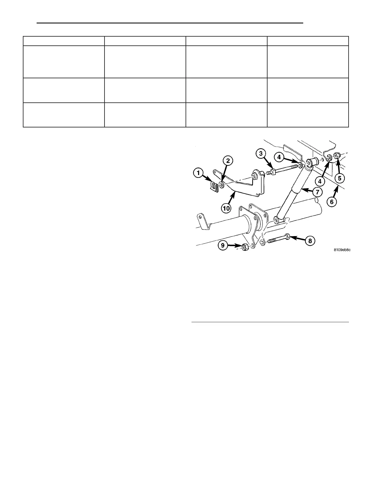
Fig. 1 SHOCK ABSORBER (LEFT SIDE SHOWN)
1 - CLIP
2 - WASHER
3 - MOUNTING STUD/BOLT
4 - WASHER
5 - NUT
6 - FRAME
7 - SHOCK ABSORBER
8 - BOLT
9 - NUT
10 - ALB LEVER
VA REAR 2 - 13