SPRI N G
DESCRIPTION
The rear suspension system u ses a mu lti-lea f
springs and a solid drive axle. The forwar d end of th e
springs are mou nted to the body ra il hangers
through r ubber bushings. The rea rwar d end of the
springs are at tached to the body by the use of shack-
les. Th e spr ing and sh ackles use r ubber bu sh ings.
OPERATION
The springs control ride qu ality an d ma intain veh i-
cle r ide heigh t. Th e shackles allow the springs to
change th eir length as the vehicle moves over va rious
road condition s.
REM OVAL
REMOVAL - (SRW)
(1) Raise and support the vehicle.
(2) Su pport the rea r axle.
(3) Remove the U-bolt and spring plat e (Fig. 2).
(4) Remove t he spring from the front spring
bracket (Fig. 2).
(5) Remove th e rea r sprin g wit h the spring sh ackle
from the spr ing bra cket (Fig. 2).
(6) Lower th e r ear axle and remove the rea r
sprin g.
(7) Remove the spr ing shackle from t he spr ing (if
needed) (F ig. 2).
REMOVAL - (DRW)
(1) Raise and support the vehicle.
(2) Su pport the rea r axle.
(3) Remove the U-bolt and spring plat e (Fig. 3).
(4) Remove t he spring from the front spring
bracket (Fig. 3).
(5) Remove th e rea r sprin g wit h the spring sh ackle
from the spr ing bra cket (Fig. 3).
(6) Lower th e r ear axle and remove the rea r
sprin g.
(7) Remove the spr ing shackle from t he spr ing (if
needed) (F ig. 3).
INSTALLATION
INSTALLATION - (SRW)
NOTE: Larger spring bushing goes toward the front.
(1) In st all the spring sha ckle t o the spr ing (if
removed) (Fig. 2). Tighten to 90 N·m (66 ft. lbs.).
(2) In st all th e sprin g to t he fr ont spring bracket
(Fig. 2). Tighten to 95 N·m (70 ft. lbs.).
(3) In st all the sprin g to the rear spr ing bracket
(Fig. 2). Tighten to 85 N·m (63 ft. lbs.).
(4) Raise the rear axle and a ttach th e spring plate
and U-bolts (Fig. 2). Tighten to 170 N·m (125 ft. lbs.).
(5) Lower th e vehicle.
Fig. 2 REAR LEAF SPRING WITH SINGLE REAR
WHEELS
1 - NUT
2 - LEAF SPRING
3 - U-BOLTS
4 - PLATE
5 - SPRING BOLT
6 - SHACKLE BOLT
7 - SPRING SHACKLE
8 - U-BOLT NUTS
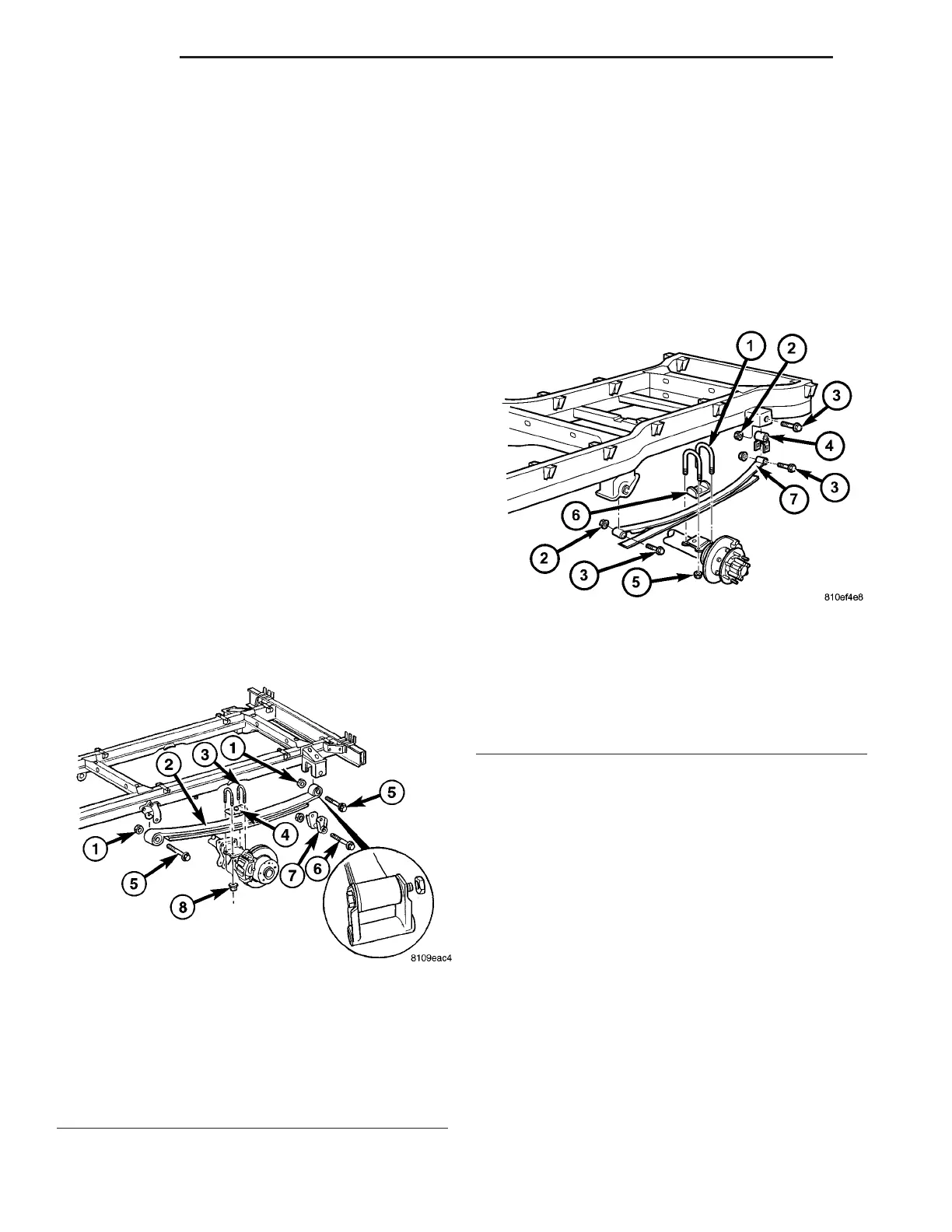
Fig. 3 REAR LEAF SPRING WITH DUAL REAR
WHEELS
1 - U-BOLTS
2 - NUT
3 - BOLT
4 - SPRING SHACKLE
5 - U-BOLT MOUNTING NUT
6 - U-BOLT BRACKET ALIGNING PLATE
7 - LEAF SPRING
2-14 REAR VA