INSTALLATION - (DRW)
NOTE: Larger spring bushing goes toward the front.
(1) In st all the spring sha ckle t o the spr ing (if
removed) (Fig. 3). Tighten to 185 N·m (136 ft. lbs.).
(2) In st all th e sprin g to t he fr ont spring bracket
(Fig. 3). Tighten to 185 N·m (136 ft. lbs.).
(3) In st all the sprin g to the rear spr ing bracket
(Fig. 3). Tighten to 185 N·m (136 ft. lbs.).
(4) Raise the rear axle and a ttach th e spring plate
and U-bolts (Fig. 3). Tighten to 170 N·m (125 ft. lbs.).
(5) Lower th e vehicle.
SPRI N G SH ACK LE
REMOVAL
(1) Raise and support the vehicle.
(2) Su pport the rea r axle.
(3) Remove both th e rea r spr ing shackles from the
spring bracket.
(4) Lower the rea r axle and rem ove the rear spring
sh ackle from the spring.
INSTALLATION
(1) In st all the sprin g sha ckle t o the spring.
Tighten t o 90 N·m (66 ft. lbs.).
(2) Raise the r ear axle wh ile installing the spring
sh ackle to the sprin g bracket. Tight en t o 85 N·m (63
ft. lbs.).
(3) Lower th e vehicle.
STABI LI Z ER BAR
REMOVAL
(1) Raise and support the vehicle.
(2) Remove the st abilizer links at the bar (Fig. 4).
(3) Remove th e stabilizer ba r clamp at t he axle
(Fig. 4).
(4) Remove the bracket (Fig. 4)
(5) Remove the st abilizer bar from the vehicle.
INSTALLATION
(1) In st all the stabilizer ba r to th e axle.
(2) In st all the st abilizer bar clamps an d bracket,
center the bar th en tighten t o 25 N·m (18ft . lbs.)
(SRW) (Fig. 4) or Tighten to 70 N·m (52 ft . lbs.) for
(DRW) (Fig. 5).
(3) In st all th e stabilizer ba r to the stabilizer lin ks
and tighten t o 95 N·m (60 ft. lbs.) (Fig. 4) or (Fig. 5).
(4) Lower th e vehicle.
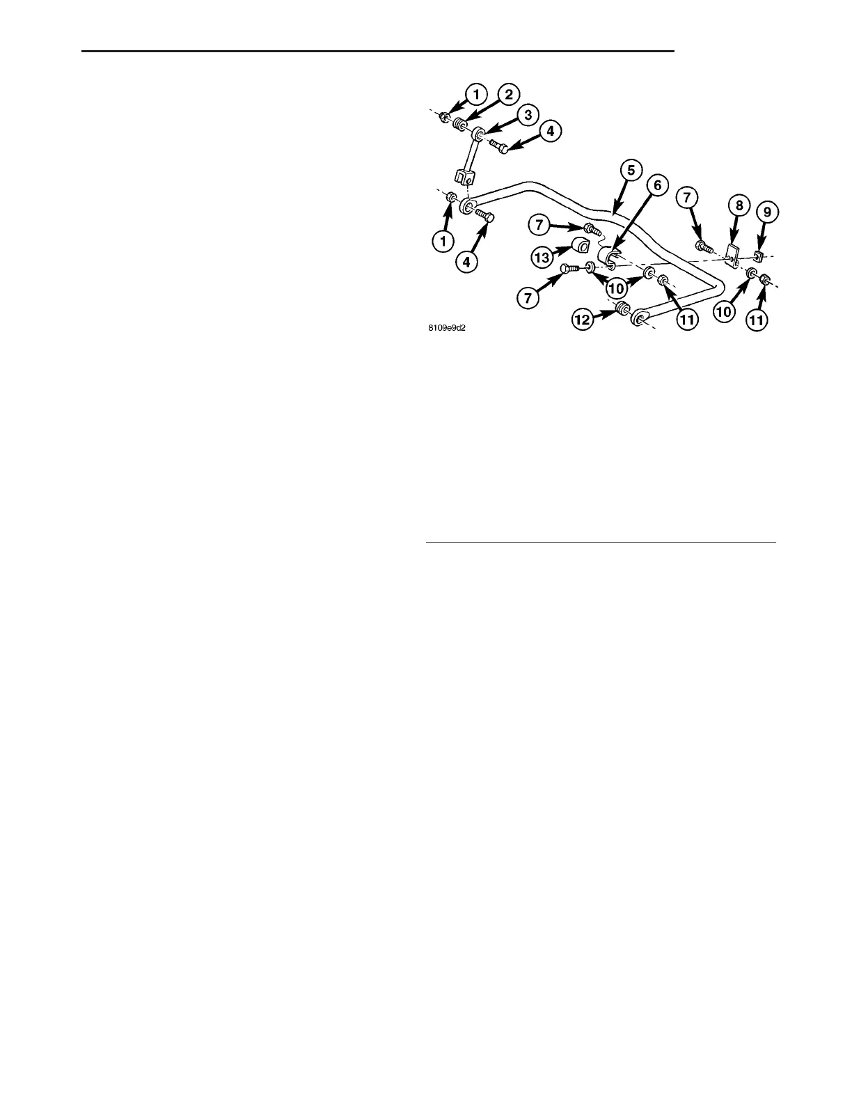
Fig. 4 SWAY BAR WITH SINGLE REAR WHEELS
(SRW)
1 - M12 NUT
2 - BUSHING
3 - SWAY BAR LINK
4 - M12 BOLT
5 - SWAY BAR
6 - CLAMP
7 - M8 BOLT
8 - BRACKET
9 - FOUR POINT NUT M8
10 - WASHER
11 - M8 NUT
12 - BUSHING
13 - MOUNT
VA REAR 2 - 15