STABI LI Z ER LI N K
REMOVAL
(1) Raise and support the vehicle.
(2) Remove the st abilizer links at the bar (Fig. 4).
(3) Remove the st abilizer link at the fr ame.
INSTALLATION
(1) In st all th e stabilizer ba r to the stabilizer lin ks
and tight en to 95 N·m (60 ft. lbs.) (Fig. 4).
(2) Lower th e vehicle.
(3) In st all the stabilizer link to the fra me. Tight en
to 95 N·m (60 ft. lbs.).
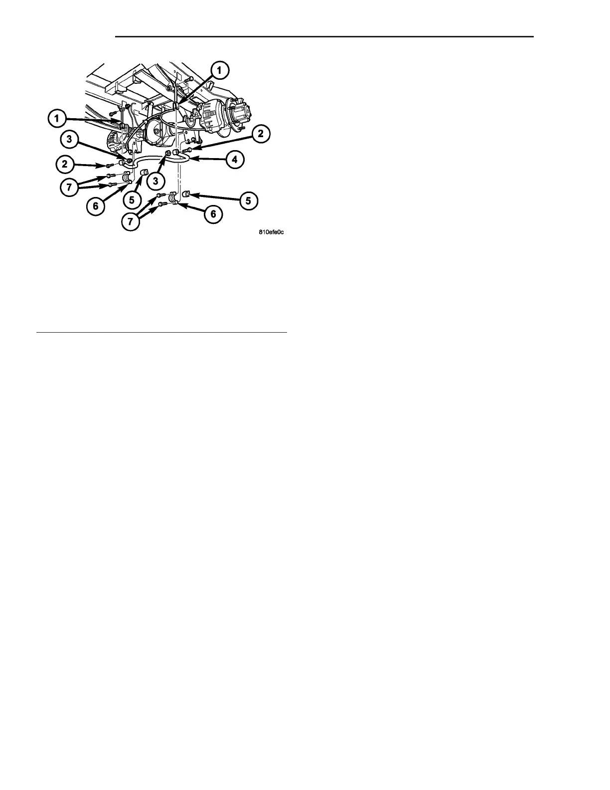
Fig. 5 SWAY BAR WITH DUAL REAR WHEELS
(DRW)
1 - STABILIZER LINK
2 - SWAY BRA BOLT
3 - SWAY BAR NUT
4 - SWAY BAR
5 - RUBBER MOUNT
6 - SWAY BAR CLAMP
7 - CLAMP MOUNTING BOLTS
2-16 REAR VA