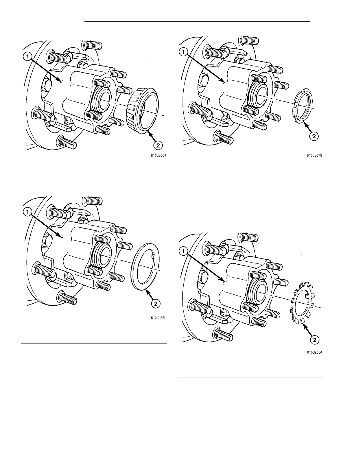
(9) In st all outer hub (1) bearing (2) (F ig. 26).
(10) Install thrust wa sher (2) (Fig. 27).
CAUTION: Thrust washer is designed for left or
right side and are not interchangeable.
(11) In st all inner hub (1) nu t (2) (Fig. 28).
(12) Tighten inner hub nut with Wrench 9290 t o
300 N·m (221 ft. lbs.) wh ile spinning th e wh eel hub
constan tly. Tur n back inner nu t and then tight en
until it touches th e thrust washer without pla y. Then
tighten 1/8 turn.
(13) Install locking plate (2) (Fig. 29).
(14) Install out er hu b n ut a nd tight en with
Wren ch 9290 to 250 N·m (184 ft. lbs.).
(15) Install axle shaft.
(16) Install br ake caliper and support .
(17) Adjust par king brakes.
Fig. 26 OUTER HUB BEARING
1 - HUB
2 - BEARING
Fig. 27 THRUST WASHER
1 - HUB
2 - WASHER
Fig. 28 INNER HUB NUT
1 - HUB
2 - NUT
Fig. 29 LOCKING PLATE
1 - HUB
2 - PLATE
3-30 REARAXLE VA