BRAK E LI N ES
STAN DARD PROCEDU RE
STANDARD PROCEDURE - ISO FLARING
A preform ed m etal brake tu be is recomm ended and
pr eferred for all r epa irs. H owever, double-wall steel
tube can be used for emergen cy repa ir when factory
repla cement pa rts ar e not readily available.
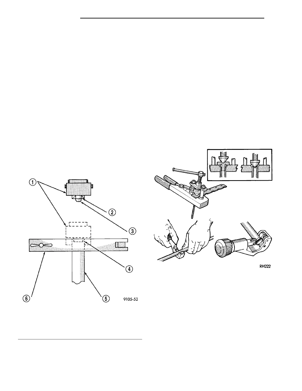
To ma ke a ISO flare use an ISO flaring tool kit.
(1) Cut off dam aged t ube with Tubin g Cutter.
(2) Remove any bur rs from th e inside of th e tube.
(3) In st all tube nut on th e tube.
(4) Position t he tube in the flaring tool flush with
the top of the tool bar (Fig. 2). Then tighten the tool
bar on the tube.
(5) In st all th e corr ect size a da pt or on th e flaring
tool yoke screw.
(6) Lubricate the adaptor.
(7) Align the ada pt or and yoke screw over the tu be
(Fig. 2).
(8) Turn the yoke screw in u ntil the a da pt or is
squar ely seated on t he tool bar.
STANDARD PROCEDURE - DOUBLE INVERTED
FLARING
A preform ed m etal brake tu be is recomm ended and
pr eferred for all r epa irs. H owever, double-wall steel
tube can be used for emergen cy repa ir when factory
repla cement pa rts ar e not readily available.
(1) Cut off dam aged t ube with Tubin g Cutter.
(2) Ream cut edges of tubing to en su re proper
flar e.
(3) In st all replacement tube nut on the tu be.
(4) In sert tube in flaring tool.
(5) Pla ce gau ge form over the end of t he tu be.
(6) Push tu bing th rough flar ing tool ja ws un til
tube contacts recessed notch in gau ge that mat ches
tube diameter.
(7) Tighten t he tool bar on the tube
(8) In sert plu g on gauge in the tube. Then swing
compression disc over gauge and cent er tapered flar-
ing screw in recess of compression disc (Fig. 3).
(9) Tighten tool ha ndle until plug gauge is
squar ely seated on jaws of fla rin g tool. This will start
the inverted flare.
(10) Remove th e plug gauge and com plete the
inverted flare.
BRAK E PADS / SH OES
REM OVAL
REMOVAL - FRONT (SRW)
(1) Unscr ew the ca p from t he bra ke flu id reservoir.
(2) Raise and support the vehicle.
(3) Remove t he front wheels (Refer to 22 - TIRES/
WHEELS/WHEELS - RE MOVAL).
(4) Remove th e wea r indicator cable an d the wear
indicator (Fig. 4).
Fig. 2 ISO Flaring
1 - ADAPTER
2 - LUBRICATE HERE
3 - PILOT
4 - FLUSH WITH BAR
5 - TUBING
6 - BAR ASSEMBLY
Fig. 3 Inverted Flare Tools
5-8 BRAKES- BASE VA