NOTE: Seal off the line ends and connection
threads in the brake calipers with plugs. Also check
brake hoses for signs of cracks.
(5) Remove the brake ca liper guide bolt (Fig. 4).
(6) Remove the brake ca liper (Fig. 4).
(7) Remove the brake pads (Fig. 4).
REMOVAL - FRONT (DRW)
(1) Unscr ew the ca p from t he bra ke flu id reservoir.
(2) Raise and support the vehicle.
(3) Remove t he front wheels (Refer to 22 - TIRES/
WHEELS/WHEELS - RE MOVAL).
(4) Remove th e wea r indicator cable an d the wear
indicator (Fig. 5).
NOTE: Seal off the line ends and connection
threads in the brake calipers with plugs. Also check
brake hoses for signs of cracks.
(5) Remove the brake ca liper guide bolt (Fig. 5).
(6) Remove the brake ca liper (Fig. 5).
(7) Remove the brake pads (Fig. 5).
REMOVAL - REAR (16” WHEELS) (SRW)
(1) Unscr ew the ca p from t he bra ke flu id reservoir.
(2) Raise and support the vehicle.
(3) Remove th e rea r wheels (Refer to 22 - TIRES/
WHEELS/WHEELS - INSTALLATION).
(4) Remove th e wea r indicator cable an d the wear
indicator (Fig. 6).
NOTE: Seal off the line ends and connection
threads in the brake calipers with plugs. Also check
brake hoses for signs of cracks.
(5) Remove the brake ca liper guide pins (Fig. 6).
(6) Remove the brake ca liper from the ca liper
adapter (Fig. 6).
(7) Remove the reta ining spr ing (Fig. 6).
(8) Remove the pa ds (F ig. 6).
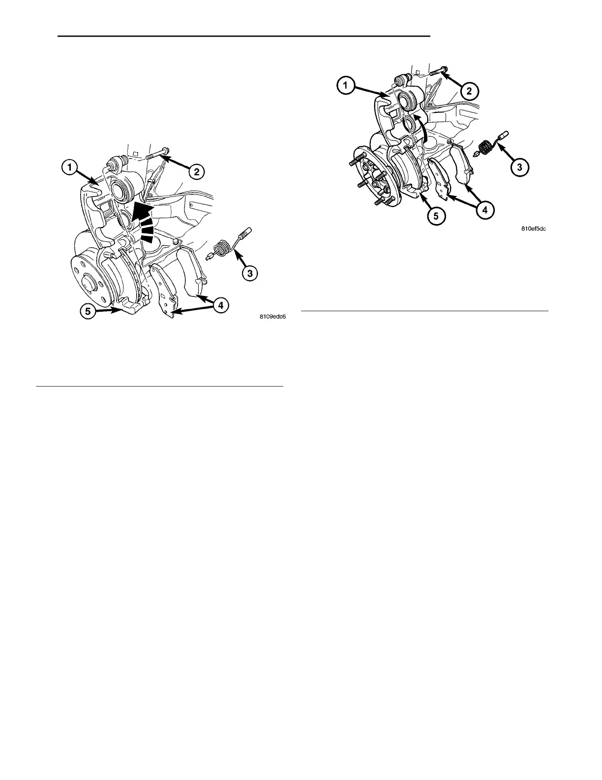
Fig. 4 FRONT BRAKE PADS
1 - DISC BRAKE CALIPER
2 - GUIDE BOLT
3 - WEAR INDICATOR
4 - DISC BRAKE PADS
5 - CALIPER ADAPTER
Fig. 5 FRONT DISC BRAKE PADS WITH DUAL
REAR WHEELS
1 - DISC BRAKE CALIPER
2 - GUIDE PIN/BOLT
3 - WEAR INDICATOR
4 - BRAKE PADS
5 - BRAKE CALIPER ADAPTER
VA BRAKES - BASE 5 - 9