INSTALLATION
INSTALLATION - FRONT (SRW)
(1) In st all the brake pads (F ig. 4).
(2) In st all the wear indica tor cable an d t he wea r
indicator (Fig. 4). Tighten t o 10 N·m (89 in. lbs.).
NOTE: Do not install the brake hose twisted and
ensure freedom of movement.
(3) In st all t he brake caliper to the brake caliper
adapter (Fig. 4). Tighten the guide bolt to 25 N·m
(221 in. lbs.).
(4) Bleed t he brake system.
(5) Check the br ake system for any leaks.
(6) In st all the front wh eels.
(7) Lower th e vehicle.
INSTALLATION - FRONT (DRW)
(1) In st all the brake pads (F ig. 5).
(2) In st all the wear indica tor cable an d t he wea r
indicator (Fig. 5). Tighten t o 10 N·m (89 in. lbs.).
NOTE: Do not install the brake hose twisted and
ensure freedom of movement.
(3) In st all t he brake caliper to the brake caliper
adapter (Fig. 5). Tighten the guide bolt to 25 N·m
(221 in. lbs.)(M8 bolt) or Tighten t he guide bolt to 30
N·m (265 in. lbs.)(M10 10.9 bolt).
(4) Bleed t he brake system.
(5) Check the br ake system for any leaks.
(6) In st all the front wh eels.
(7) Lower th e vehicle.
INSTALLATION - REAR (16” WHEELS) (SRW)
(1) In st all the brake pads (F ig. 6).
(2) In st all the wear indica tor cable an d t he wea r
indicator (Fig. 6). Tighten t o 10 N·m (89 in. lbs.).
NOTE: Do not install the brake hose twisted and
ensure freedom of movement.
(3) In st all th e bra ke caliper t o brake ca liper
adapter (F ig. 6). Tighten the gu ide pins t o 25 N·m
(221 in. lbs.) for M8 bolt or 30 N·m (266 in. lbs.) for
M10 bolt.
(4) In st all the retaining spr ing (Fig. 6).
(5) In st all th e rea r wh eels (Refer t o 22 - TIRES/
WHEELS/WHEELS - INSTALLATION).
(6) Lower th e vehicle.
INSTALLATION - REAR (16” WHEELS) (SRW)
(1) In st all the brake pads (F ig. 7).
(2) In st all the wear indica tor cable an d t he wea r
indicator (Fig. 7). Tighten t o 10 N·m (89 in. lbs.).
NOTE: Do not install the brake hose twisted and
ensure freedom of movement.
(3) In st all th e bra ke caliper t o brake ca liper
adapter (Fig. 7). Tigh ten the guide pin to 30 N·m
(266 in. lbs.) for M10 bolt.
(4) In st all th e rea r wh eels (Refer t o 22 - TIRES/
WHEELS/WHEELS - INSTALLATION).
(5) Lower th e vehicle.
INSTALLATION - REAR (DRW)
(1) In st all the brake pads (F ig. 8).
(2) In st all the wear indica tor cable an d t he wea r
indicator (Fig. 8). Tighten t o 10 N·m (89 in. lbs.).
NOTE: Do not install the brake hose twisted and
ensure freedom of movement.
(3) In st all th e bra ke caliper t o brake ca liper
adapter (F ig. 8). Tighten the gu ide pins t o 25 N·m
(221 in. lbs.) for M8 bolt or 30 N·m (266 in. lbs.) for
M10 10.9 bolt.
(4) In st all the retaining spr ing (Fig. 8).
(5) In st all th e rea r wh eels (Refer t o 22 - TIRES/
WHEELS/WHEELS - INSTALLATION).
(6) Lower th e vehicle.
DI SC BRAK E CALI PERS
REM OVAL
REMOVAL - FRONT (SRW)
(1) Unscr ew the ca p from t he bra ke flu id reservoir.
(2) Raise and support the vehicle.
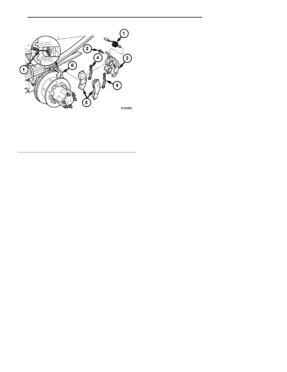
Fig. 8 REAR DISC BRAKE PADS WITH DUAL REAR
WHEELS
1 - WEAR INDICATOR
2 - GUIDE PIN/BOLT
3 - DISC BRAKE CALIPER
4 - RETAINING SPRING
5 - DISC BRAKE PADS
6 - CALIPER ADAPTER
VA BRAKES - BASE 5 - 11