REMOVAL - REAR (DRW)
(1) Unscr ew the ca p from t he bra ke flu id reservoir.
(2) Raise and support the vehicle.
(3) Remove th e rea r wheels (Refer to 22 - TIRES/
WHEELS/WHEELS - INSTALLATION).
(4) Remove th e wea r indicator cable an d the wear
indicator (Fig. 12).
NOTE: Seal off the line ends and connection
threads in the brake calipers with plugs. Also check
brake hoses for signs of cracks.
(5) Remove the brake hose a t the br ake caliper
(Fig. 12).
(6) Remove the brake ca liper guide bolt (Fig. 12).
(7) Remove the brake ca liper (Fig. 12).
INSTALLATION
INSTALLATION - FRONT (SRW)
(1) In st all t he brake caliper to the brake caliper
adapter (F ig. 9). Tighten the gu ide pins t o 25 N·m
(221 in. lbs.).
NOTE: Do not install the brake hose twisted and
ensure freedom of movement.
(2) In st all the brake hose at the brake caliper (Fig.
9). Tighten t he bolt to 14 N·m (124 in. lbs.).
(3) In st all the wear indica tor cable an d t he wea r
indicator (Fig. 9). Tighten t o 10 N·m (89 in. lbs.).
(4) Bleed t he brake system.
(5) Check the br ake system for any leaks.
(6) In st all the front wh eels.
(7) Lower th e vehicle.
INSTALLATION - FRONT (DRW)
(1) In st all t he brake caliper to the brake caliper
adapter (Fig. 10). Tighten the guide pins to 25 N·m
(221 in . lbs.)(M8 bolt) or Tighten the guide pins to 30
N·m (265 in. lbs.)(M10 10.9 bolt).
NOTE: Do not install the brake hose twisted and
ensure freedom of movement.
(2) In st all the brake hose at the brake caliper (Fig.
10). Tight en the bolt to 14 N·m (124 in . lbs.).
(3) In st all the wear indica tor cable an d t he wea r
indicator (Fig. 10). Tighten to 10 N·m (89 in. lbs.).
(4) Bleed t he brake system.
(5) Check the br ake system for any leaks.
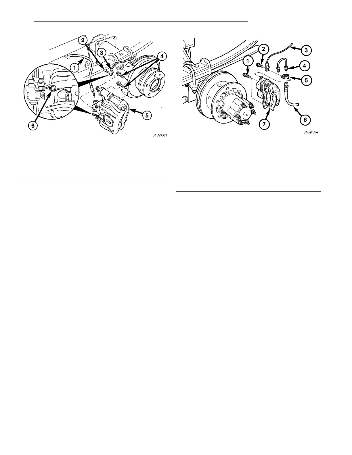
Fig. 11 REAR DISC BRAKE CALIPER
1 - BRAKE HOSE
2 - BANJO BOLT
3 - WEAR INDICATOR
4 - CALIPER ADAPTER BOLTS
5 - DISC BRAKE CALIPER
6 - WEAR INDICATOR
Fig. 12 REAR DISC BRAKE CALIPER WITH DUAL
REAR WHEELS
1 - ADAPTER BOLT
2 - WEAR INDICATOR MOUNTING BOLT
3 - WEAR INDICATOR
4 - BRAKE LINE
5 - CLAMP
6 - BRAKE HOSE
7 - BRAKE CALIPER
VA BRAKES - BASE 5 - 13