(3) Check the br ake system for any leaks.
(4) Reconnect t he electrical connect or to th e bra ke
fluid level indica tor (Fig. 14).
ALB LEV ER
REMOVAL
(1) Raise and support the vehicle.
(2) Remove the reta ining clip for the ALB lever
(Fig. 15).
(3) Remove the bolt for the lever at the axle (F ig.
15).
(4) Remove the lever.
INSTALLATION
(1) In st all the lever to t he vehicle.
(2) In st all t he lower mou nting bolt to th e axle (Fig.
15).
(3) In st all t he lever t o the shock bolt and then
insta ll the clip (Fig. 15).
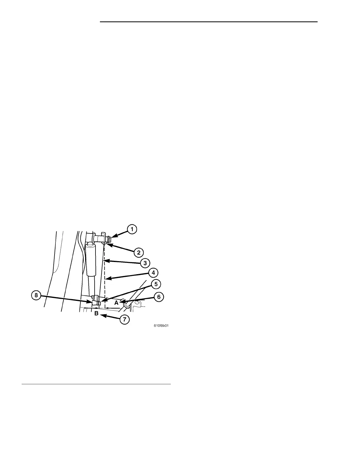
(4) Check th e side deflection of t he ALB lever with
a st raight edge fr om P oint-A to Poin t-B as the
gra phic shows. Max deflection play of the actuator
rod sh ould be no more th an 15 mm (.60 in) (Fig. 15).
(5) Lower th e vehicle.
ALB CON T ROLLER
REMOVAL
(1) In st all th e brake pedal rod to hold the bra ke
pressure.
(2) Raise and support the vehicle.
(3) Remove th e brake lines t o the (automat ic load-
dependant br ake pressure control) ALB cont roller.
(4) Remove th e adjusting nut and t he spring from
the ALB controller.
(5) Remove the mounting bolts.
(6) Remove the ALB controller.
INSTALLATION
(1) In st all the ALB controller to the veh icle.
(2) In st all the moun ting bolt s for t he cont roller.
(3) In st all the brake lines. Tighten th e lines to 16
N·m (142 in. lbs.)
(4) In st all t he adjusting r od, nut and sprin g to the
ALB controller.
(5) Lower th e vehicle.
(6) Remove the brake peda l hold down rod.
(7) Fill and bleed the brake syst em (Refer to 5 -
BRAKES - STANDARD PROCE DURE ).
(8) Raise t he vehicle and adjust th e ALB con troller
(Refer to 5 - BRAKES/H YDRAULIC/MECH ANICAL/
ALB CONTROLLER - ADJ USTME NTS).
(9) Lower th e vehicle a nd test drive.
ADJ U ST M EN T S
ADJUSTMENT
(1) Clean any debris awa y from the test por ts caps
at the ALB controller.
(2) Connect brake adapters special tool 9297 to t he
test ports a t the ALB contr oller.
(3) In st all a Pressure Ga uge, Special Tool
C-4007-A, t o the adapter s.
(4) Tighten a ll tube nut fittings to 17 N·m (145 in.
lbs.) torque.
(5) Bleed an y air out of the system . This inclu des
bleeding th e air from the hose between t he pressure
test fitting an d pressure gau ge, which is done at th e
pressure gau ge.
NOTE: Adjustment is determined for the automatic
load-dependent brake power control system accord-
ing to the ALB plate. This is housed in the stowage
compartment under the front passenger’s door
panel. The part number of the rear spring is
stamped into the spring eye. This must correspond
to the part number of the rear spring on the ALB
plate.
(6) To a ccura tely adjust the rea r axle load you
must fir st det ermine the r ear axle load by weighing
the vehicle a t a local scale.
(7) In st all the brake pedal win ch Special tool 9296
bet ween t h e br a ke peda l a n d t h e dr iver sea t a n d
slowly t urn the dia l until the specified inlet br ake
pr essu re is indicated a t the gauge.
Fig. 15 ALB LEVER DEFLECTION
1 - CLIP
2 - SPRING
3 - LEVER
4 - STRIAGHT EDGE
5 - NUT
6 - POINT -A
7 - POINT - B
8 - SUSPENSION POINT
5-16 BRAKES-BASE VA