NOTE: The pressure gauge, connected at the ALB
controller must indicate the outlet pressure which
is assigned on the ALB plate to the rear axle load
determined.
NOTE: If the rear axle load determined is between
two figures indicated on the ALB plate, the outlet
pressure should be determined accordingly.
(8) If the pressure measured differs fr om the spec-
ifica tion, adju st t he ALB con troller (Fig. 16).
(9) Loosen the brake peda l winch.
(10) Adjust th e out let pressure by turnin g the
adju st ing nut (Fig. 16) To i n c r e a s e p re s s u r e -
tighten the adjusting nut. To reduce pressure -
loos en th e a dju stin g n ut.
(11) After adjustment rein stall the br ake pedal
winch an d recheck th e pressu res and readj u st if
needed.
(12) Tighten the lock adjusting nut.
MASTER CYLINDER
DIAGNOSIS AND TESTING - MASTER CYLIN-
DER / POWER BOOSTER
(1) St art engine an d check boost er vacuum h ose
connect ions. A hissing noise indica tes vacu um leak.
Correct any vacu um lea k before proceeding.
(2) St op engine an d shift transmission into Neu-
tral.
(3) Pump brake peda l until all vacuum reserve in
booster is depleted.
(4) Press and hold brake pedal u nder light foot
pr essu re. The peda l sh ould hold firm, if t he pedal
falls a way m aster cylinder is faulty (inter nal leak-
age).
(5) St art engine a nd n ote pedal a ction. It should
fall away slightly under light foot pressur e then hold
firm. If n o pedal a ction is discernible, power booster,
vacu um supply, or v a cuum ch eck va lve is fa ulty. Pro-
ceed to t he POWER BOOSTER VACUUM TEST.
(6) If the POWER BOOSTER VACUUM TEST
pa sses, rebuild booster vacuum reserve as follows:
Relea se brake pedal. Increa se en gine speed to 1500
rpm, close th e throttle and immediately turn off ign i-
tion to st op engine.
(7) Wait a m inimum of 90 secon ds and try brake
action again. Booster sh ould provide two or m ore vac-
uum assist ed peda l a pplicat ions. If va cuum assist is
not provided, booster is faulty.
POWER BOOSTER VACUUM TEST
(1) Connect vacuu m gauge to booster check valve
with short length of hose a nd T-fit ting (Fig. 17).
(2) St art and run engine at curb idle speed for one
minute.
(3) Observe the vacuum su pply. If va cuum supply
is not adequ ate, repair vacuum supply.
(4) Clam p h ose shut between va cuum sour ce and
check valve.
(5) St op engine a nd observe va cuum gauge.
(6) If vacu um drops more tha n one in ch HG (33
millibars) with in 15 seconds, boost er diaphr agm or
check valve is faulty.
POWER BOOSTER CHECK VALVE TEST
(1) Disconn ect vacu um hose from ch eck valve.
(2) Remove check valve a nd va lve seal from
booster.
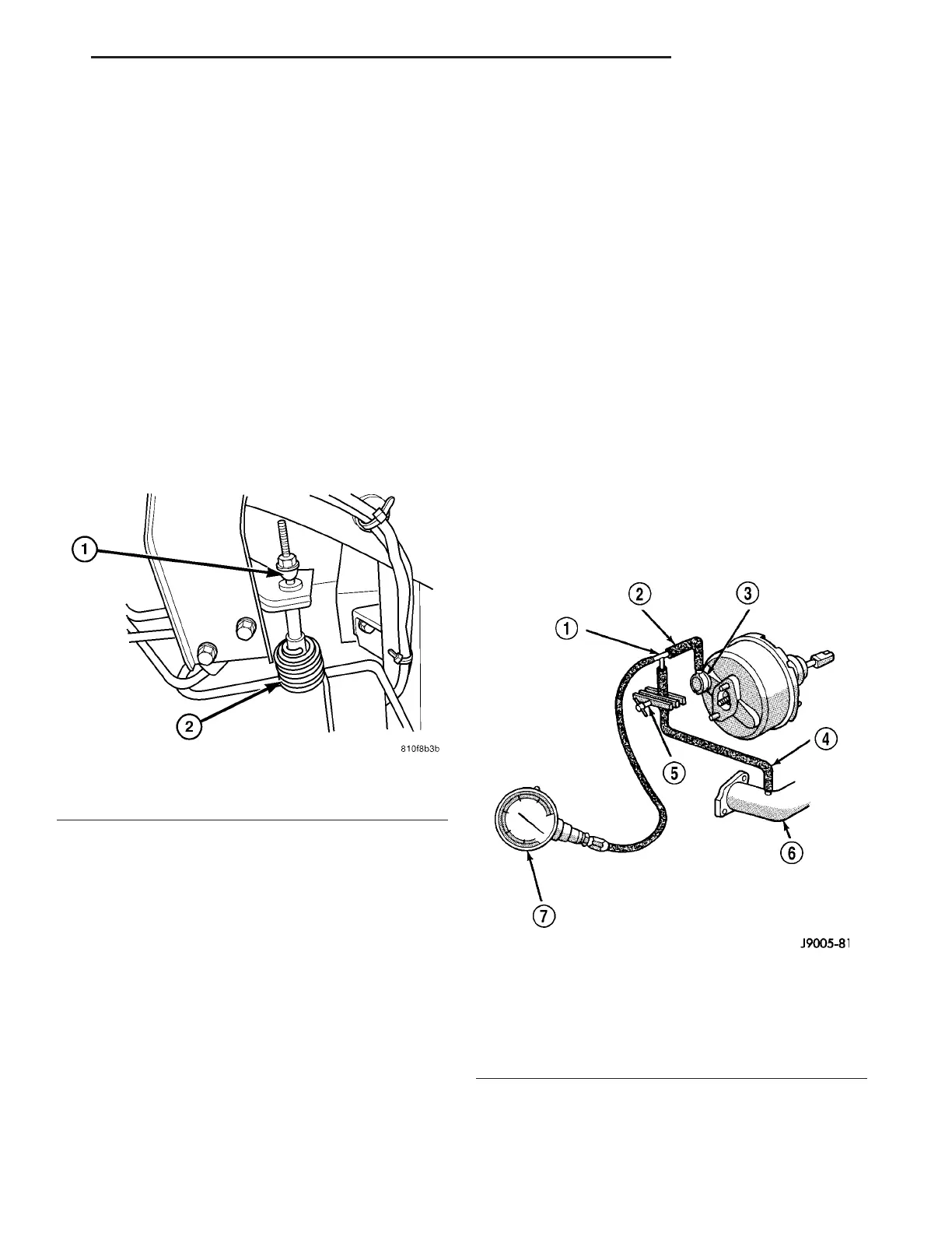
Fig. 16 ALB CONTROLLER ADJUSTER NUT
1 - ALB ADJUSTER NUT
2 - SPRING
Fig. 17 Typical Booster Vacuum Test Connections
1 - TEE FITTING
2 - SHORT CONNECTING HOSE
3 - CHECK VALVE
4 - CHECK VALVE HOSE
5 - CLAMP TOOL
6 - INTAKE MANIFOLD
7 - VACUUM GAUGE
VA BRAKES - BASE 5 - 17