to deter mine a decelera tion rat e tha t would indicate
a possible wheel-locking ten dency.
The sign al stren gth of any magn etic in duction sen-
sor is direct ly a ffected by:
• Ma gnet ic field strength; the st ronger the mag-
netic field, th e stron ger the sign al
• Num ber of windin gs in the sen sor ; mor e wind-
ings provide a stron ger signal
• Excit er ring speed; the fast er the exciter ring/
tone wheel rotates, the stron ger th e sign al will be
• Distance between the exciter ring teet h an d
WSS; th e closer th e WSS is to t he exciter ring/tone
wheel, the stronger the sign al will be.
FRON T WH EEL SPEED SEN -
SOR
REMOVAL
(1) Raise and support the vehicle.
(2) Remove the front wh eels.
(3) Pull the wh eel speed sensor out of th e fron t
wheel hub (Fig. 2).
(4) On ly d o t h i s s t e p i f s e ns o r rep l a c e m ent i s
n e c e ss a ry. Cu t t hrough the wheel speed sensor
cable at an ea sily accessible point (Fig. 2).
(5) Remove clam ping sleeve from the knuckle if
da maged or being replaced with new sensor (Fig.
2).
INSTALLATION
(1) Connect separa te wheel speed sensor cables
with shrink-fit sleeves and shrink-fit t ubin g (F ig. 2).
On l y d o t h i s s t e p i f rep l a c ing t h e s ens o r.
(2) In st all the clamping bushing in to the knuckle
(Fig. 2) On ly d o t h i s s t e p i f re p l a c ing t h e s ens o r
or the clamping bushing was damaged.
(3) In st all th e wh eel speed sensor all t he way into
the front wheel hu b th e wh eel speed sensor will self
adju st when th e vehicle is moved (Fig. 2).
(4) In st all the front wh eels.
(5) Lower th e vehicle.
REAR WH EEL SPEED SEN SOR
REMOVAL
(1) Raise and support the vehicle.
(2) Remove the rear wheels.
(3) Pull the wheel speed sensor out of the mou nt-
ing hole in th e axle support ing tube (Fig. 3).
(4) On ly d o t h i s s t e p i f s e ns o r rep l a c e m ent i s
n e c e ss a ry. Cu t t hrough the wheel speed sensor
cable at an ea sily accessible point (Fig. 3).
(5) Remove clam ping sleeve from the knuckle if
da maged or being replaced with new sensor (Fig.
3).
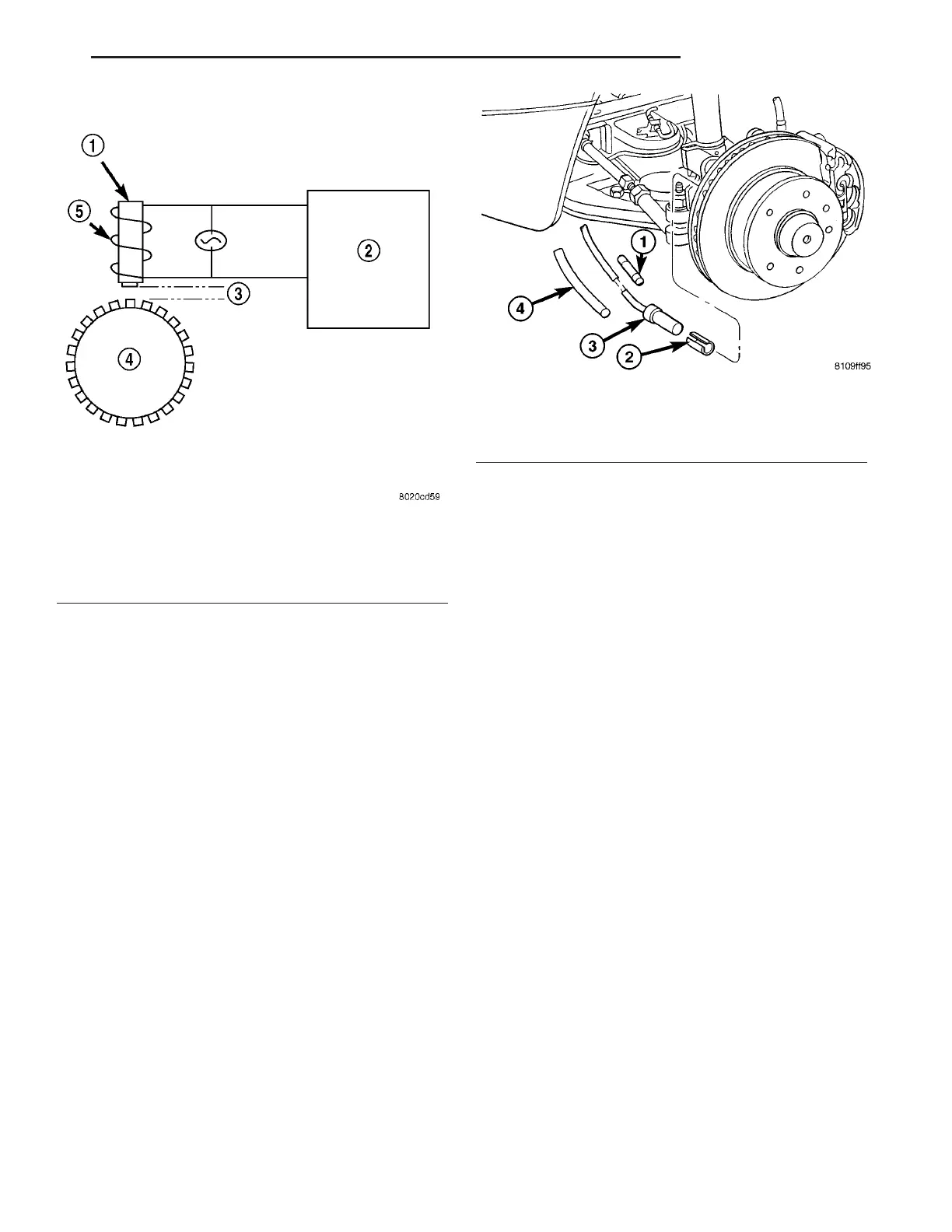
Fig. 1 Operation of the Wheel Speed Sensor
1 - MAGNETIC CORE
2 - CAB
3 - AIR GAP
4 - EXCITER RING
5 - COIL
Fig. 2 FRONT WHEEL SPEED SENSOR
1 - SHRINK-FIT SLEEVE
2 - CLAMPING BUSHING
3 - SPEED SENSOR
4 - SHRINK TUBE
VA BRAKES - ABS 5 - 31